
Frequency Compensation Scheme for Stabilizing the LDO Using External NPN in HV Domain

a frequency compensation and ldo technology, applied in the direction of electric variable regulation, process and machine control, instruments, etc., can solve the problems of unstable voltage regulators, not always practical for voltage regulator circuits and given loads,

Inactive Publication Date: 2010-08-26
MICROCHIP TECH INC
View PDF4 Cites 28 Cited by
  • Summary
  • Abstract
  • Description
  • Claims
  • Application Information

AI Technical Summary

Benefits of technology

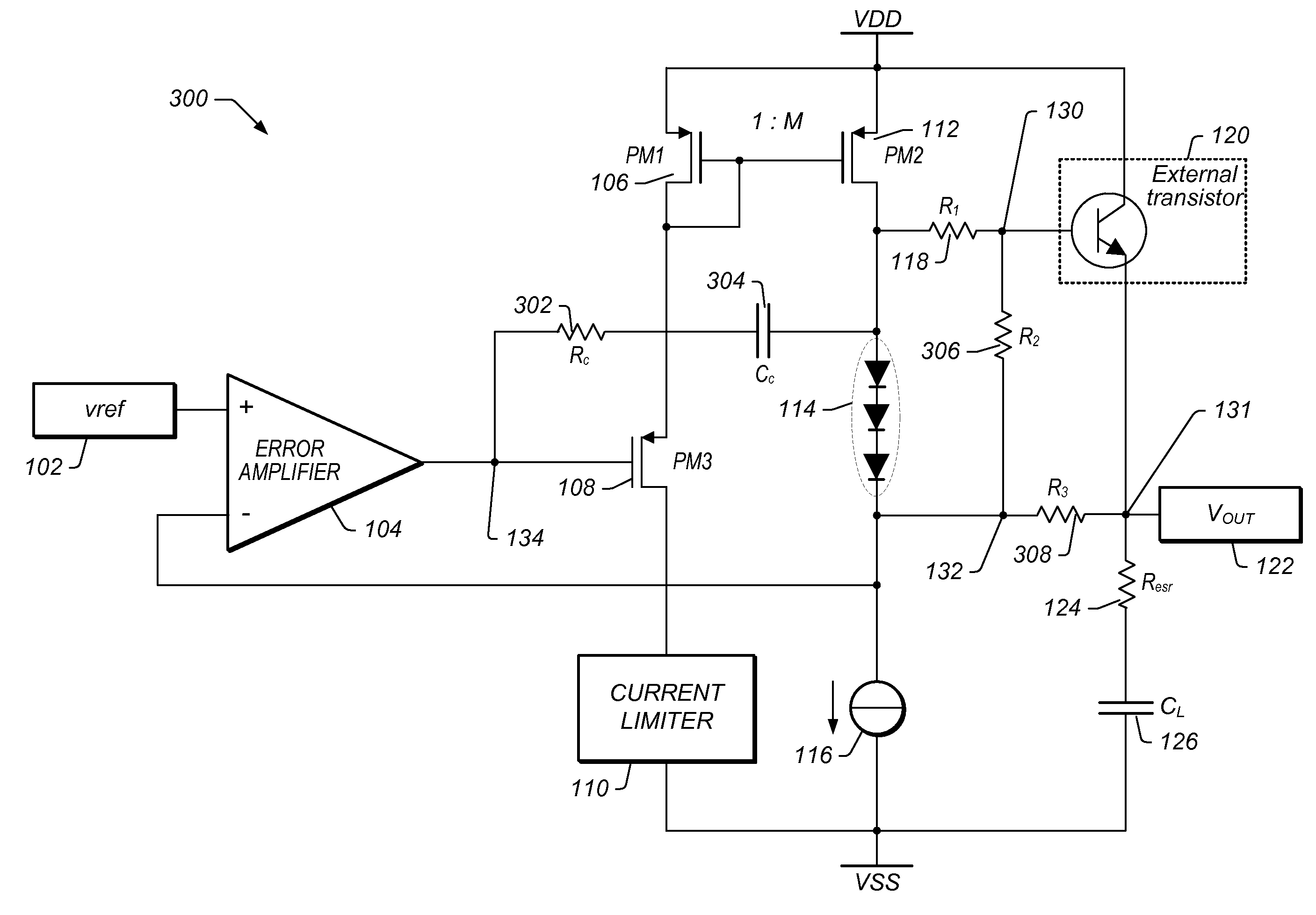
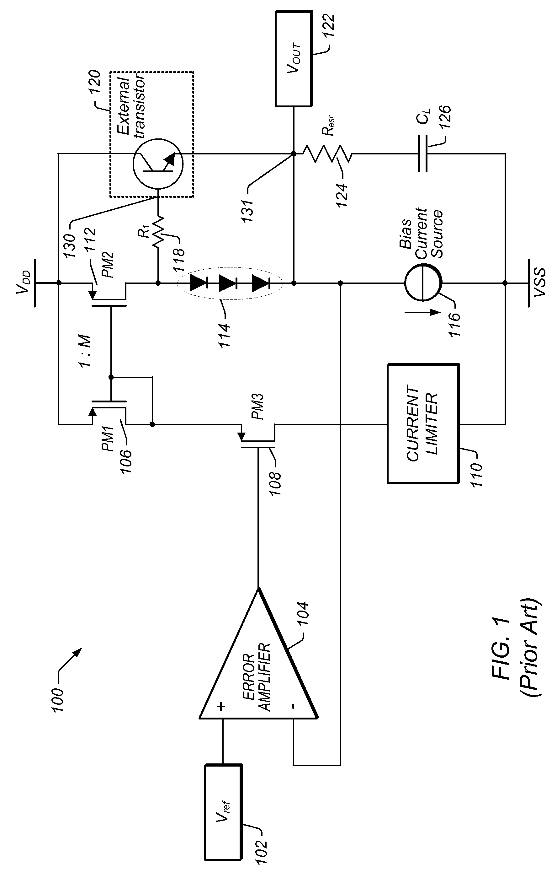
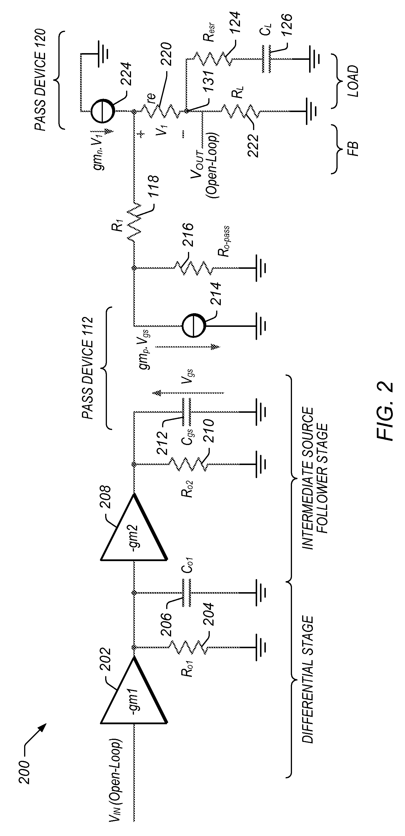
[0008]In one set of embodiments, a voltage regulator may comprise a regulator output configured to provide a regulated voltage, built around an error amplifier powered by a supply voltage and having a first input configured to receive a reference signal. A source-follower stage may be controlled by the output of the error amplifier to mirror a multiple of the current flowing in the source-follower stage into an internal pass device. A voltage developed by the mirror current (which is a multiple of the current flowing in the source-follower stage) may be used to control an external pass device configured to deliver the load current to the regulator output. A first resistor may be configured to decouple a load capacitor coupled between the regulator output and reference ground, when the load current is below a specified value, such as when the load current initially begins to rise (from a zero value, for example). A second resistor may be configured to create a bias current in the internal pass device even when the external pass device is close to cut-off region (i.e. it is not providing a load current into the regulator output. In one set of embodiments, a third resistor may be configured to counter the effects of negative impedance at the control terminal of the external pass device caused by the current-gain of the external pass device.

Problems solved by technology

However, this may not always be practical for a given voltage regulator circuit and a given load.
As the load current quickly rises from no current to maximum load current, the voltage regulator may become unstable.

Method used


Image

  • Frequency Compensation Scheme for Stabilizing the LDO Using External NPN in HV Domain
  • Frequency Compensation Scheme for Stabilizing the LDO Using External NPN in HV Domain
  • Frequency Compensation Scheme for Stabilizing the LDO Using External NPN in HV Domain

Examples


Embodiment Construction

[0018]As used herein, the term “nominal value” is used to denote an expected, stable value. For example, the nominal value of a first supply voltage is used to denote the final, stable value reached by the first supply voltage. While the term “nominal” typically refers to a specified theoretical value from which an actual value may deviate ever so slightly, in order to simplify references to certain voltage values detailed herein, “nominal value” is used to refer to the final, expected stable value reached by a supply voltage. For example, as used herein, when a supply voltage has a nominal value of 3.3V, it means that the supply voltage is configured to settle and reside at a value of 3.3V. Of course, the actual value of the supply voltage may deviate ever so slightly from this value, and the term “nominal value” is meant to account for such deviations. Furthermore, as referenced herein, a “low load current” is expected to be in the range of a few μA (microamps), while a “high load...


PUM


Abstract

A voltage regulator may comprise a regulator output configured to provide a regulated voltage, which may be controlled by an error amplifier based on the regulated voltage and a reference voltage. The error amplifier may control a source-follower stage to mirror a multiple of the current flowing in the source-follower stage into an internal pass device. A voltage developed by the mirror current may control an external pass device configured to deliver the load current into the regulator output. A first resistor may be configured to decouple a load capacitor coupled between the regulator output and reference ground, when the load current is below a specified value. A second resistor may be configured to create a bias current in the internal pass device even when the external pass device is close to cut-off region. A third resistor may be configured to counter the effects of negative impedance at the control terminal of the external pass device caused by the current-gain of the external pass device. A compensation capacitor and resistor may be coupled in series between the output of the error amplifier and the output of the voltage regulator to provide frequency compensation for the Miller-Effect.

Description

BACKGROUND OF THE INVENTION[0001]1. Field of the Invention[0002]This invention relates generally to the field of semiconductor circuit design, and more particularly to the design of improved power regulators.[0003]2. Description of the Related Art[0004]Many electronic power supplies feature voltage regulators, or regulator circuits, designed to automatically maintain a constant output voltage level to effectively provide a steady voltage to the electronic circuit to which power is being supplied, typically referred to as the load. More particularly, the object of a voltage regulator circuit is to maintain a steady output voltage regardless of current drawn by the load. Most present day voltage regulators operate by comparing the actual output voltage to a fixed—typically internal—reference voltage. The difference between the actual output voltage and reference voltage is amplified, and used for controlling a regulation element, to form a negative feedback servo control loop. The reg...

Claims


Application Information

Patent Timeline
Patent Type & Authority Applications(United States)
IPC IPC(8): G05F1/00
CPCG05F1/575
Inventor PULIJALA, SRINIVAS K.MCLEOD, SCOTT C.
Owner MICROCHIP TECH INC
Learn More