Stripline antenna and antenna array for a magnetic resonance device

a magnetic resonance device and antenna array technology, applied in the direction of instruments, magnetic measurements, measurement devices, etc., can solve the problems of deterioration of tuning behavior, reconstruction errors, deterioration of snr, etc., and achieve the effect of advantageously simplifying the antenna structure and high packing density

Inactive Publication Date: 2010-08-26
MAX PLANCK GESELLSCHAFT ZUR FOERDERUNG DER WISSENSCHAFTEN EV
View PDF24 Cites 30 Cited by
  • Summary
  • Abstract
  • Description
  • Claims
  • Application Information

AI Technical Summary

Benefits of technology

[0033]A further advantage of the invention resides in the variability in the selection of the configuration of the conductor loop of the conductor loop arrangement. If the conductor loop in accordance with one variation of the invention forms a single ring or a single polygon, the structure of the antenna is advantageously simplified. In accordance with a modified variation, the at least one conductor loop can be provided in accordance with the invention with several rings or polygons which are disposed e.g. in the direction of the strip line of the strip line resonator and can be interrupted by a tuning network. The conductor loops comprise conductor portions which form a geometric loop shape.
[0034]In particular, the loop shape can comprise a so-called ladder form, in which lateral conductor portions form straight or curved spars and central conductor portions form straight or curved rungs. It can also be advantageous to interrupt connection pieces between conductor portions in a capacitive manner or with a tuning network. The conductor loop arrangement can consist alternatively of several ladder forms having at least three rungs, wherein the adjacent spars can be formed at a predetermined spaced interval, in an overlapping manner or by means of a common spar.
[0035]Further possible formations which deviate from the classic ladder form and which have shapes deviating from a rectangular shape or circular shape are expressly incorporated into the invention. The loop shape can comprise in particular a so-called chain shape, in which conductor portions are disposed in shape of a rhombus.
[0036]For example, several simple loops or double loops (so-called “figure-of-8-coils”) or their mixed arrangements can be provided in the longitudinal or transverse direction of the strip line resonator. A double loop or “figure-of-8-coil” is generally a conductor loop, whose conductors in particular in the form of rings or polygons form a topological shape with two holes. A line which follows the progression of the “figure-of-8-loop” can be mapped onto the shape of the figure “8”. The “figure-of-8-coil” can comprise e.g. a box shape having two square loops.
[0037]It is thus possible to provide a conductor loop arrangement having several conductor loops which form independent, separately controllable, resonant structures, so that the term conductor loop arrangement can also refer to an array of individual resonators. In accordance with the invention, it is also possible to add to the strip line resonator in particular several separate conductor loop arrangements inside and / or outside the dielectric of the strip line resonator, e.g. in the form of further conductor loops or as a ladder form structure or in an alternating fashion (e.g. simple loop and ladder form structure), with a spaced interval or in a partially overlapping manner and thus create an array of individual resonators, e.g. in the longitudinal direction of the strip line resonator. If at least one of the conductor loops comprises a ladder form and at least one further conductor loop comprises a simple loop (in particular a ring or polygon), advantages can be achieved in the specific application for the variability of the adjustment of the antenna sensitivity.
[0038]The array of individual resonators does not necessarily have to extend spatially along a straight line but can also extend along a curved line or a traverse. Such variable antennas for an MR-device in the form of a linear array can also be disposed repeatedly next to one another perpendicular to the direction of the above-described one-dimensional array and in this manner a two-dimensional array is acquired. Since the extension in this direction also does not necessarily have to extend along a straight line, a three-dimensional array having a very high packing density can thus also be created. The geometric shape of this type of three-dimensional array can also be adapted to the shape of the organs (areas) to be examined, which leads to optimum conditions both for the irradiation of the HF and also in the reception.

Problems solved by technology

However, the field of view (FOV) also becomes greatly restricted.
In the case of the conventional array antennas, the coupling between the individual partial antennas plays a significant role, as it can lead to a deterioration of the tuning behavior, a deterioration of the SNR and to reconstruction errors.
The above-described arrays based upon coils have the general disadvantage that a large amount of outlay is required to produce the arrays having a relatively large number of partial antennas.
Their construction is very complicated particularly in the case of a high coil packing density.
The calibration of the coils is also frequently very difficult.
Specifically in the case of relatively high MR-frequencies, in which the antenna dimensions are in the order of magnitude of the wavelength, it becomes impossible to adjust antennas on the basis of coils.
However, in comparison with coils, strip line antennas are faced with the drawbacks of lower penetration depth and weakly pronounced sensitivity variation in the direction of the strip lines, which in particular prevents or at the very least greatly impedes accelerated image acquisition in the direction of the strip lines.
Although resonators which are constructed from strip lines can be optimized to a certain extent in terms of penetration depth, e.g. by increasing the thickness of the dielectric, these endeavors are subject to limits, since in the case of higher substrate thicknesses these arrangements can no longer be operated in the quasi-TEM-mode (Lee R F, Hardy C J, Sodickson D K, Bottomley P A. Lumped-element planar strip array (LPSA) for parallel MRI. Magn. Reson. Med. 2004; 51: 172-183).
However, these control options disclosed therein are of a “static” nature, i.e. they cannot simply be modified during the experiment.
Thus, although by displacing the sinusoidal intensity distribution in the direction of the strip lines, it is possible in combination with geometric measures to optimize the geometric characteristics of the intensity profile, in terms of the requirements of the sensitivity profile in the direction of the strip lines for accelerated image acquisition, optimum values are not achieved by these measures.
In the overlapping areas, capacitances having a detrimental effect (in particular an increase in the capacitive coupling between the individual antennas) are inevitably formed between the individual conductors.
The elements can no longer be controlled independently of each other.
However, the sheet antenna proposed in US 2005 / 0024054 A1 in conjunction with the annular conductor proposed therein is not suitable without additional measures for use in the production of arrays owing to the strong coupling.

Method used


Image

  • Stripline antenna and antenna array for a magnetic resonance device
  • Stripline antenna and antenna array for a magnetic resonance device
  • Stripline antenna and antenna array for a magnetic resonance device

Examples


Embodiment Construction

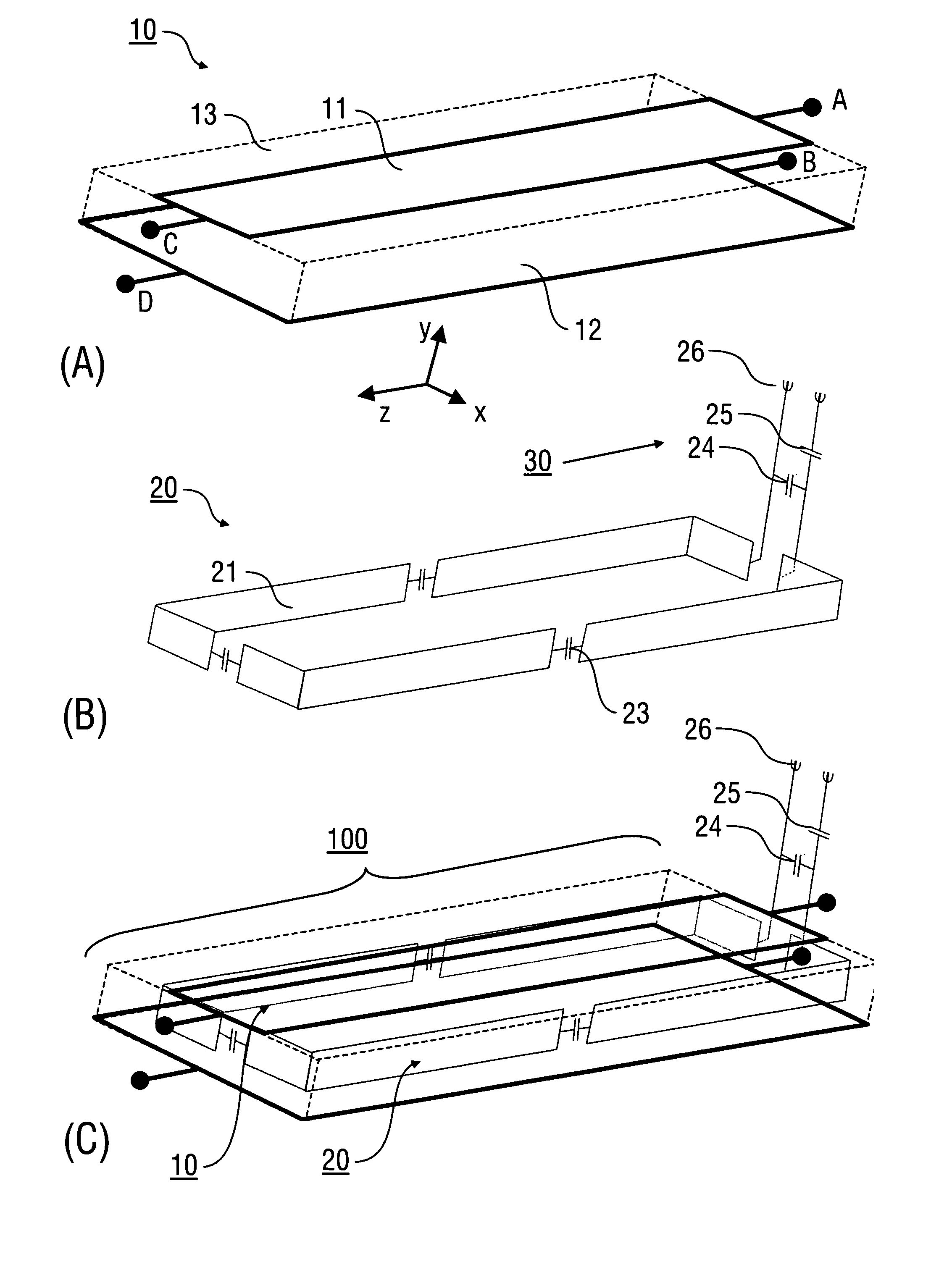
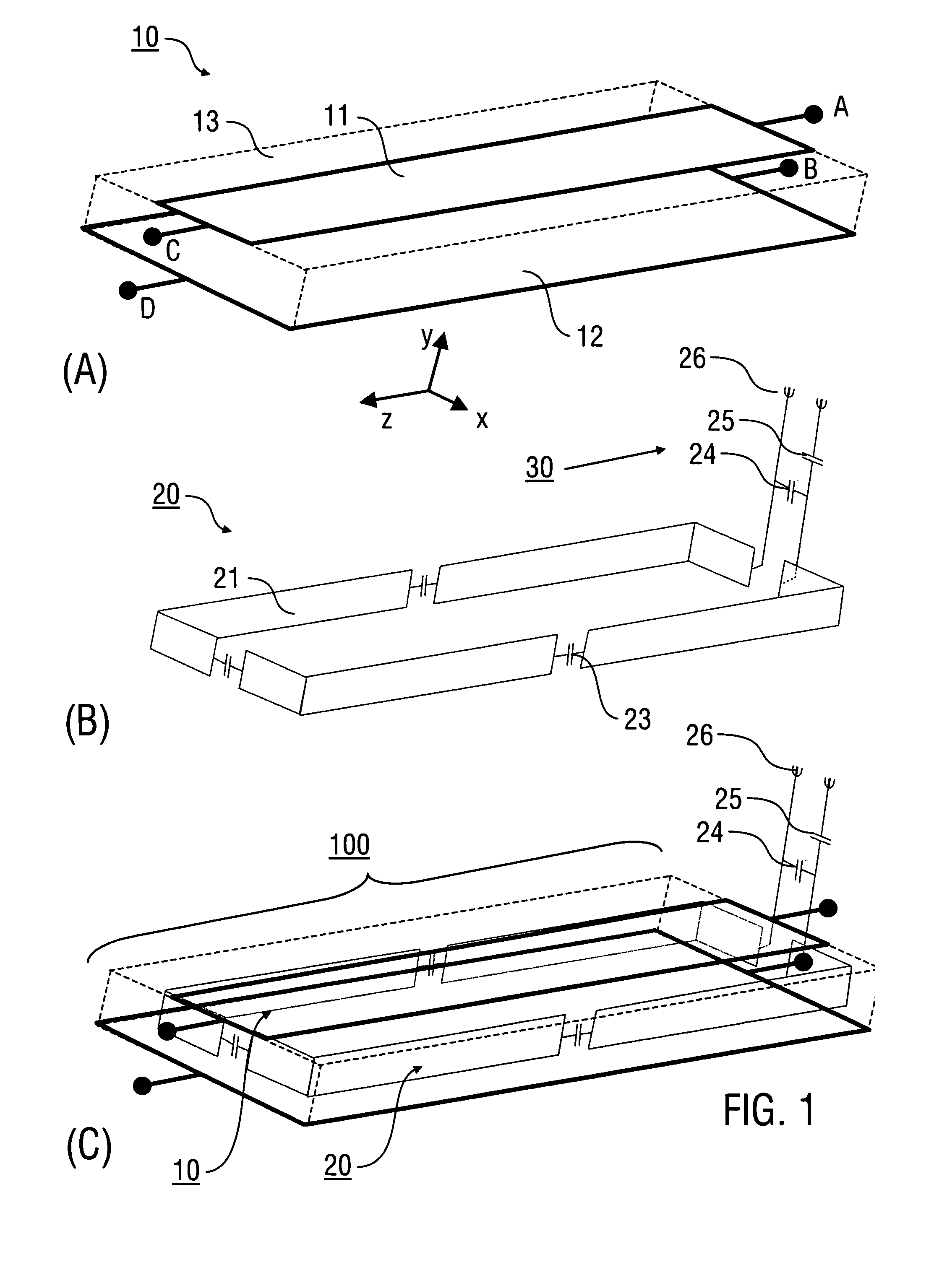
[0065]Embodiments of the invention are described hereinafter with reference by way of example to antennas, whose conductor loop arrangement comprises at least one rectangular conductor loop having a conductor or conductor portions in the form of a layered strip and / or a bar, e.g. a round bar. The implementation of the invention is not restricted to the illustrated examples, but can be accomplished in a corresponding manner with conductor loop arrangements which comprise differently formed conductor loops and / or conductors having a different cross-section. Furthermore, deviating from the illustration the conductor of the conductor loop arrangement can comprise an angle, which differs from 90°, relative to the strip line resonator. Furthermore, the invention is described hereinafter with reference by way of example to antennas having a strip line resonator, which extend along a planar reference surface (reference plane). Accordingly, the invention can be implemented with curved refere...


PUM


Abstract

An antenna (100) for a magnetic resonance device has a predetermined sensitivity and is designed to excite and/or detect a magnetic resonance in an object under test. The antenna (100) includes a stripline resonator (10) that is equipped with at least one stripline (11), and a conductor loop arrangement (20) that adjoins the stripline resonator (10) and forms at least one conductor loop (21, 22, 28) which is interrupted by at least one capacitor (23). The sensitivity of the antenna (100) is formed by overlapping sensitivity profiles of the stripline resonator (10) and the conductor loop arrangement (20). Also described are an antenna array (200) including a plurality of antennas (100), a magnetic resonance device (300) including at least one antenna (100) or antenna array (200), and methods for magnetic resonance imaging or magnetic resonance spectroscopy.

Description

SUBJECT MATTER OF THE INVENTION[0001]The invention relates to an antenna for a magnetic resonance device (MR-device), in particular an antenna having the features of the preamble of claim 1. The invention also relates to an antenna array for an MR-device and to a method of operating the MR-device. The main application of the invention is for magnetic resonance imaging (MRI) and for magnetic resonance spectroscopy.PRIOR ART[0002]Magnetic nuclear resonance has become established as an important imaging and analysis method, in particular in medicine. This method makes use of the fact that magnetic nuclear moments in the static magnetic field can be deflected when electromagnetic energy of a defined frequency is radiated. The frequency is determined from the strength of the static magnetic field and the gyromagnetic constant of the atom nuclei examined. The nuclear moments which precede coherently as a result of the excitation generate a magnetic induction signal which can be registered...

Claims


Application Information

Patent Timeline
Patent Type & Authority Applications(United States)
IPC IPC(8): G01R33/34
CPCG01R33/3415G01R33/345G01R33/5659G01R33/3635G01R33/3453
Inventor DRIESEL, WOLFGANGMOELLER, HARALD
Owner MAX PLANCK GESELLSCHAFT ZUR FOERDERUNG DER WISSENSCHAFTEN EV
Why Eureka
Try Eureka