Plastic waveguide-fed horn antenna

Inactive Publication Date: 2010-08-26
RGT UNIV OF CALIFORNIA
View PDF13 Cites 248 Cited by
  • Summary
  • Abstract
  • Description
  • Claims
  • Application Information

AI Technical Summary

Benefits of technology

[0036]As such, this plastic, low-cost manufacturing process may be used to replace the expensive metallic component

Problems solved by technology

However, such antennas using metallic components are expensive to manufacture.
270-275, 2006), such a technique is not available for 3D antennas.
Therefore, while known techniques exist for the manufacture of 3D metallic horn anten

Method used


Image

  • Plastic waveguide-fed horn antenna
  • Plastic waveguide-fed horn antenna
  • Plastic waveguide-fed horn antenna

Examples


Example

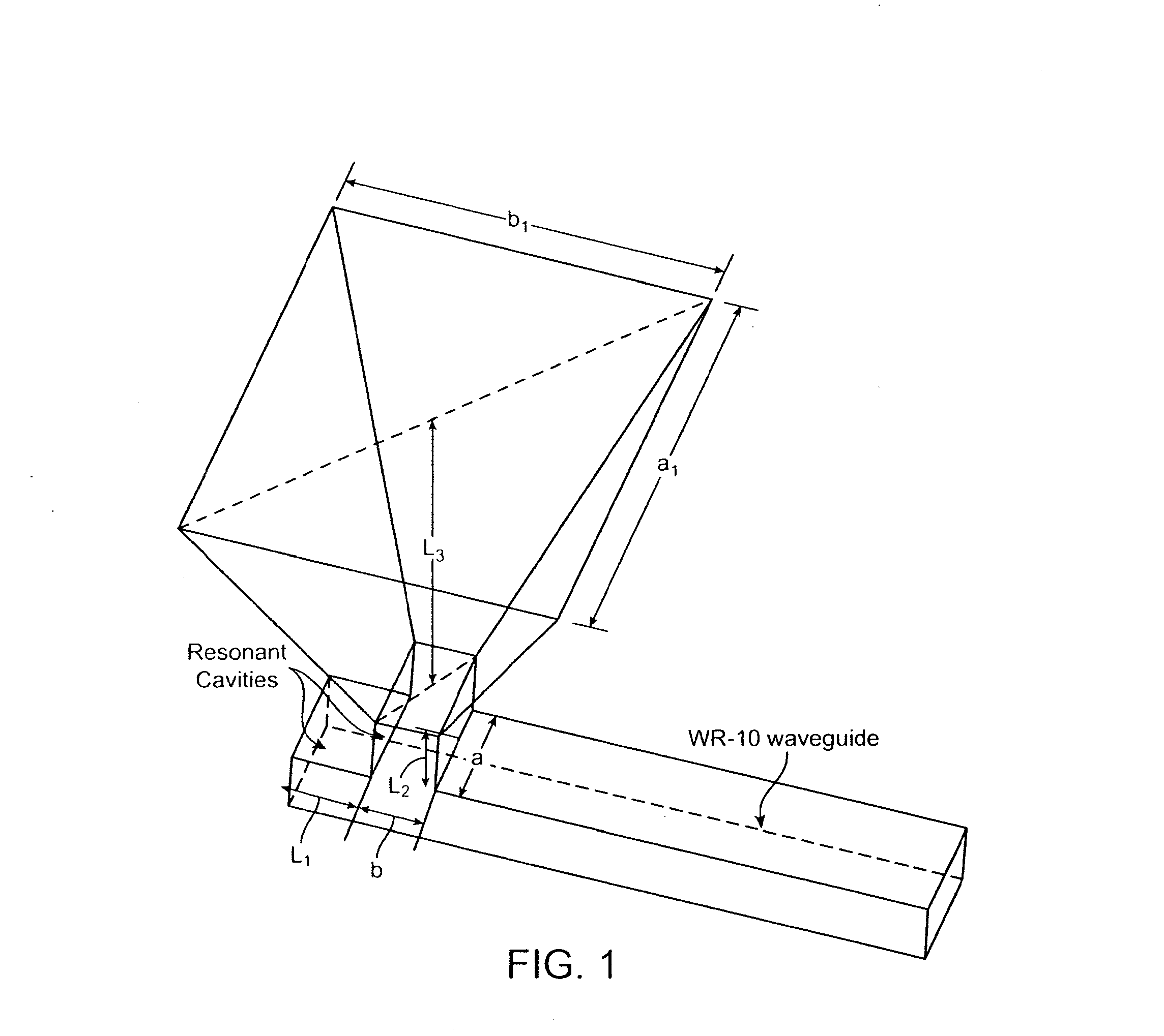
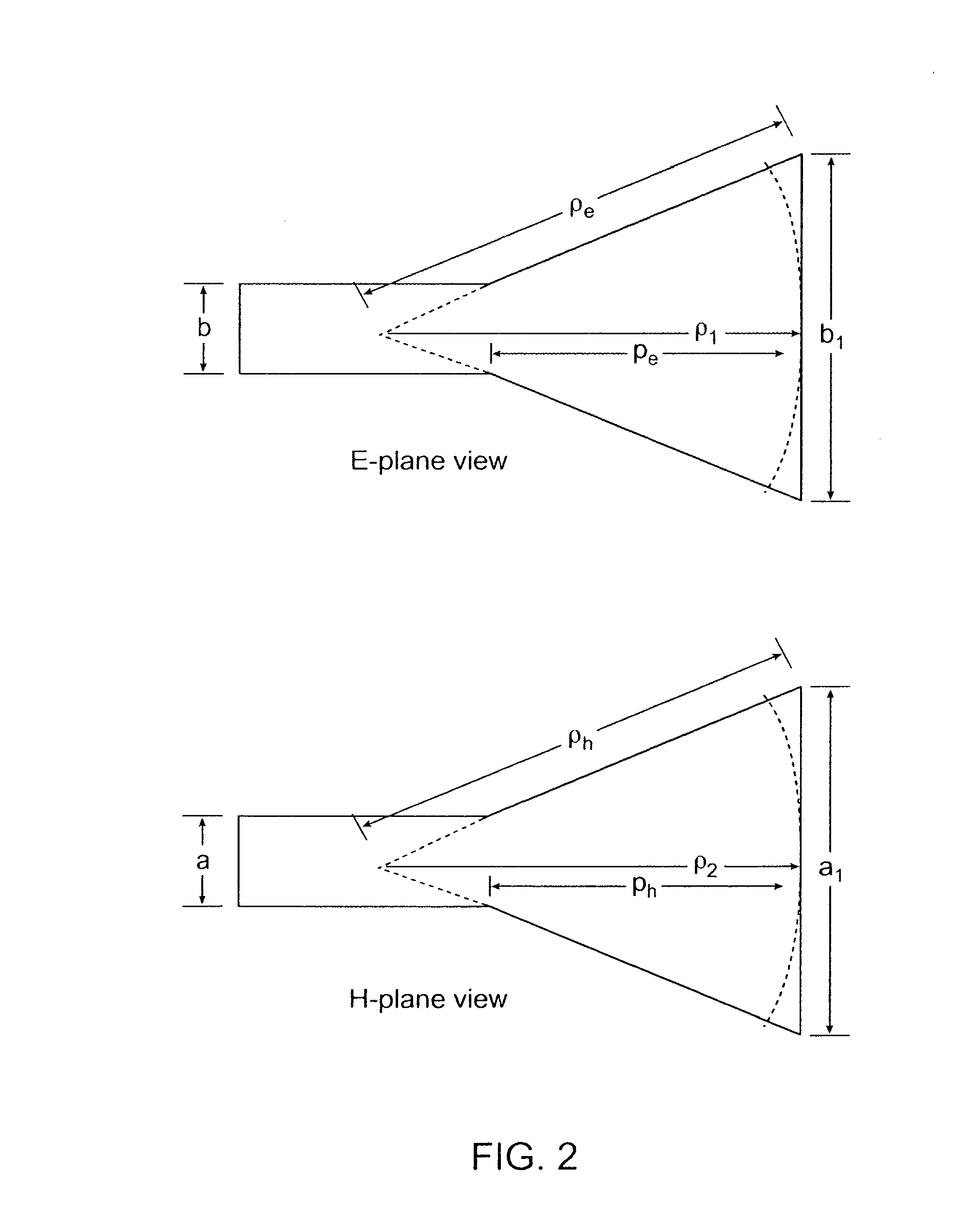
[0053]FIG. 1 shows the schematic diagram of a waveguide-fed horn antenna. A pyramidal horn, which is flared in both the E- and H-planes, is used. The radiation characteristics of a pyramidal horn are a combination of the E- and H-plane cross sectional views shown in FIG. 2. The design of the pyramidal horn can use the optimum gain method by specifying the dimensions of the waveguide and the desired antenna gain. In order to physically realize a pyramidal horn, the height of the pyramidal horn, L3 in FIG. 1 (PH or PE in FIG. 2) can be given by (see, Constantine A. Balanis, Antenna Theory: Analysis and Design, (John Wiley, 1997), pp. 651-721):

pH=(a1-a)[(ρHa1)2-14]1 / 2(1)pE=(b1-b)[(ρEb1)2-14]1 / 2(2)

[0054]The gain, Go, of a horn antenna is related to its physical area and the operation wavelength, λ, and is given as follows (see, Constantine A. Balanis, Antenna Theory: Analysis and Design, (John Wiley, 1997), pp. 651-721):

Go=124πλ2(a1b1)(3)

[0055]The maximum directivity for the H-plane hor...


PUM

PropertyMeasurementUnit
Thicknessaaaaaaaaaa
Lengthaaaaaaaaaa
Sizeaaaaaaaaaa

Abstract

A plastic, waveguide-fed, horn antenna is manufactured using a three-dimensional (3D), polymeric micro hot embossing process. Two cavity resonators may be designed to reduce the impedance mismatch between the pyramidal horn antenna and the feeding waveguide. The waveguide-fed antenna may be fabricated using a self-aligned 3D plastic hot embossing process followed by a selective electroplating and sealing process to coat an approximately 8 μm-thick gold layer around the internal surfaces of the system. As such, this plastic, low-cost manufacturing process may be used to replace the expensive metallic components for millimeter-wave systems and provides a scalable and integrated process for manufacturing an array of antenna.

Description

CROSS-REFERENCES TO RELATED APPLICATIONS[0001]The present application claims priority to U.S. Provisional Patent Application No. 60 / 856,188, filed Nov. 1, 2006, the teachings of which are incorporated herein by reference.STATEMENT AS TO RIGHTS TO INVENTIONS MADE UNDER FEDERALLY SPONSORED RESEARCH AND DEVELOPMENT[0002]A part of this invention was made with Government support under Grant (Contract) No. DMI-0428884 awarded by the National Science Foundation. The Government has certain rights to this invention.BACKGROUND OF THE INVENTION[0003]The present invention relates to antenna devices, and particularly to methods for manufacturing antenna devices.[0004]An antenna is a key element in radar systems for applications in airplanes, astronomy and other detectors (see, e.g., J. B. Mead, A. L. Pazmany, S. M. Sekelsky, and R. E. McIntosh, “Millimeter-wave radars for remotely sensing clouds and precipitation,”Proceedings of the IEEE, vol. 82, no. 12, pp. 1891-1906, December 1994). Millimete...

Claims


Application Information

Patent Timeline
IPC IPC(8): H01Q13/02C25D3/48
CPCC25D5/44H01Q13/0225C25D5/56H01Q13/02
Inventor SAMMOURA, FIRASLIN, LIWEI
Owner RGT UNIV OF CALIFORNIA
Why Eureka
Try Eureka