
Spatial light modulator and display apparatus

Active Publication Date: 2010-08-26
IGNITE INC
View PDF42 Cites 12 Cited by
  • Summary
  • Abstract
  • Description
  • Claims
  • Application Information

AI Technical Summary

Benefits of technology

[0022]An aspect of the present invention is to provide an image projection system with new and improved configuration to implement control processes to achieve a reduction in the initiating voltage for controlling and operating a deflectable mirror. The new and improved configurations and control processes further prevent stiction of the deflectable mirror to the electrodes functioning as stoppers and further prevent the deflectable mirror from jumping. The improvements in mirror operations can be achieved without requiring a more complicate control process of applying the control voltages to an address electrode or requiring a more complex mirror element structure.

Problems solved by technology

Even though there have been significant advances made in recent years in the technologies of implementing electromechanical micromirror devices as spatial light modulators (SLM), there are still limitations and difficulties when they are employed to display high quality images.
Specifically, when the display images are digitally controlled, the quality of the images is adversely affected because the images are not displayed with a sufficient number of gray scale gradations.
The on-and-off states of the micromirror control scheme as that implemented in the U.S. Pat. No. 5,214,420, and in most conventional display systems, impose a limitation on the quality of the display.
Due to the ON-OFF states implemented in the conventional systems, there is no way of providing a shorter pulse width than the duration represented by the LSB.
The limited levels of gray scale lead to a degradation of the display image.
However, if a larger number of pixels is packaged in a chip of a certain size to increase the definition of an image, the size of each pixel becomes proportionately smaller, and thus reducing the size of the transistor of a memory cell controlling the address electrode(s) and equipped within the aforementioned pixel, lowering the withstanding voltage and making it very difficult to secure a voltage to generate the necessary magnitude of the Coulomb force.
Further, if the initiating voltage is high, there is a greater probability of the occurrence of stiction, a phenomenon in which the mirror becomes inoperable by being stuck to the address electrode, and there is also the technical problem of the mirror jumping greatly at the end of a shift, as a result of the speed of collision increasing when the mirror shifts to the address electrode on the ON or OFF side.
Specifically, in a countermeasure against the above described problems in which the electric potentials of the address electrode connected to memory are changed, the memory access speed needs to be increased, the difficulty of which increases with the number of pixels.
Further, the conventional techniques disclosed in the patents and patent applications listed above do not provide a single electrode with a countermeasure to stiction or to the above described jumping of the mirror, thus requiring separate electrodes for the above described countermeasures as well as requiring a reduced initiating voltage, all of which creates unnecessarily increases the complexity of the structure of a pixel.

Method used


Image

  • Spatial light modulator and display apparatus
  • Spatial light modulator and display apparatus
  • Spatial light modulator and display apparatus

Examples


Embodiment Construction

[0141]The following is a description, in detail, of the preferred embodiment of the present invention with reference to the accompanying drawings.

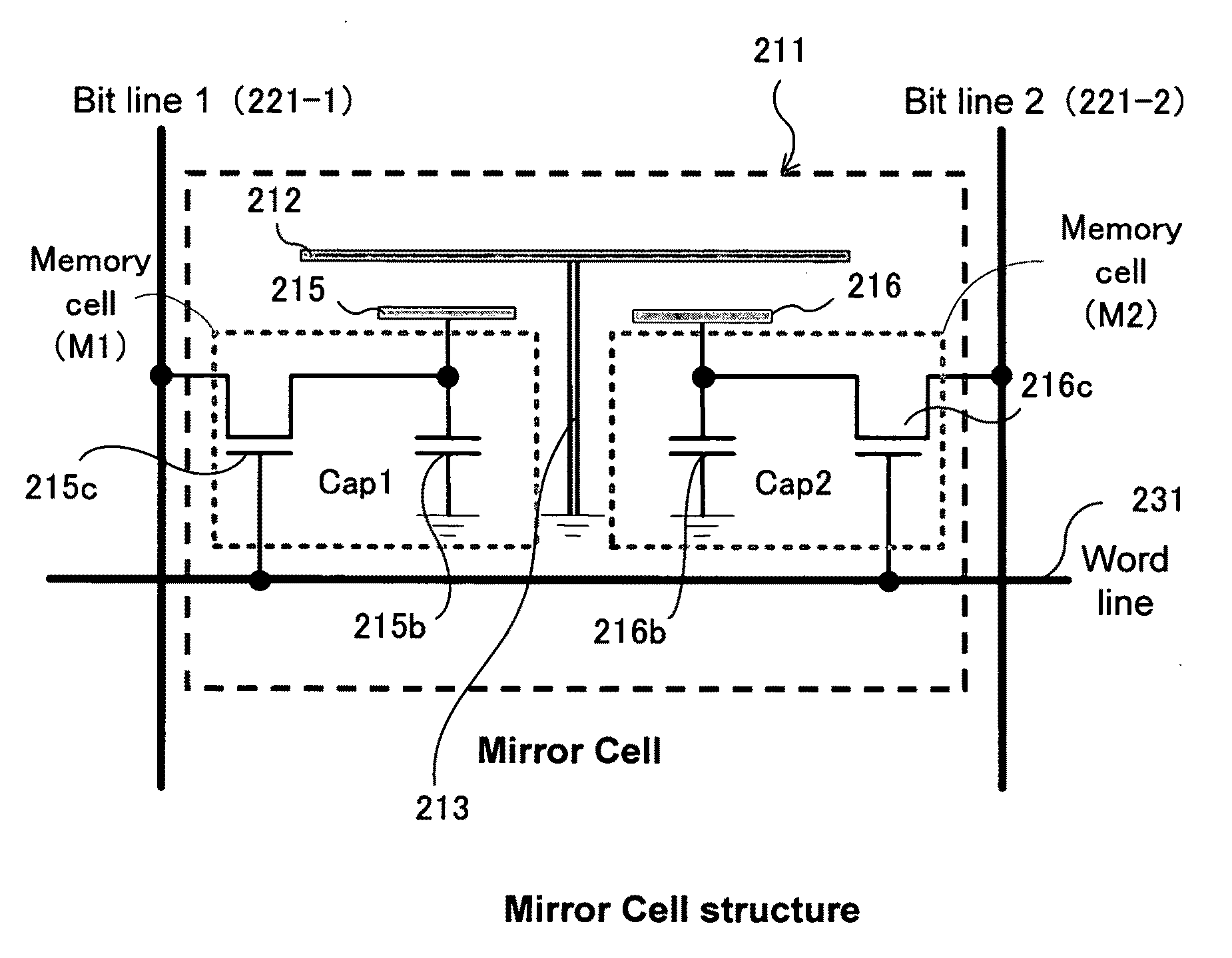
[0142]FIG. 2 is a functional block diagram showing an exemplary configuration of a display system according to a preferred embodiment of the present invention. FIG. 3 is a block diagram showing an exemplary configuration of a spatial light modulation element implemented in a display system according to a preferred embodiment of the present invention. FIG. 4 is a functional circuit diagram showing an exemplary configuration of a pixel unit 211 implemented in a spatial light modulator according to the present embodiment.

[0143]The projection apparatus 100 according to the present embodiment comprises a spatial light modulator 200, a control apparatus 300, a light source 510 and a projection optical system 520.

[0144]FIG. 5 is a top view diagram showing a diagonal perspective of a spatial light modulator in which multiple mirror elements (i.e.,...


PUM


Abstract

The present invention provides an image projection system comprising a spatial light modulator (SLM) comprises a plurality of pixel elements, wherein each of the pixel elements further comprises a deflectable mirror, and at least a first electrode and a second electrode for controlling the deflectable mirror to deflect to different tilt angles to reflect and modulate an illumination light for displaying an image; and a controller for applying a voltage to the second electrode wherein the voltage applied in an initial operation period is different from the voltage applied in an image display period.

Description

CROSS REFERENCE TO RELATED APPLICATIONS[0001]This application is a Non-Provisional Application of Application 61 / 192,528 and claims the Priority Date of Sep. 18, 2008. This Application is also a Continuation-in Part (CIP) Application of a co-pending Non-provisional application Ser. No. 12 / 004,607 filed on Dec. 24, 2007. application Ser. No. 12 / 004,607 is a Continuation-in Part (CIP) Application of a U.S. patent application Ser. No. 11 / 121,543 filed on May 4, 2005, now issued into U.S. Pat. No. 7,268,932. The application Ser. No. 11 / 121,543 is a Continuation in part (CIP) Application of three previously filed Applications. These three Applications are Ser. No. 10 / 698,620 filed on Nov. 1, 2003; Ser. No. 10 / 699,140 filed on Nov. 1, 2003, now issued into U.S. Pat. No. 6,862,127; and Ser. No. 10 / 699,143 filed on Nov. 1, 2003 now issued into U.S. Pat. No. 6,903,860 by one of the Applicants of this Patent Application. The disclosures made in these Patent Applications are hereby incorporate...

Claims


Application Information

Patent Timeline
IPC IPC(8): G02B26/00
CPCG02B26/0841H04N9/3105H04N9/3197H04N9/312H04N9/3111
Inventor SUGIMOTO, NAOYAMAEDA, YOSHIHIROISHII, FUSAO
Owner IGNITE INC
Features
  • Generate Ideas
  • Intellectual Property
  • Life Sciences
  • Materials
  • Tech Scout
  • Unparalleled Data Quality
  • Higher Quality Content
  • 60% Fewer Hallucinations
Learn More