Microfluidic Chip and Method Using the Same

a microfluidic chip and microfluidic technology, applied in the field of tissue culture devices, can solve the problems of liver tissue cells dying, fresh medium cannot be efficiently diffused into liver tissues, and inability to efficiently culture liver tissues, etc., and achieve the effect of efficiently culture tissues in vitro

Active Publication Date: 2010-08-26
NATIONAL TSING HUA UNIVERSITY
View PDF5 Cites 26 Cited by
  • Summary
  • Abstract
  • Description
  • Claims
  • Application Information

AI Technical Summary

Benefits of technology

[0007]The objective of the present invention is to provide a microfluidic chip to efficiently culture tissues in vitro.
[0014]Preferably, the connected position between two of adjacent microfluidic channels has a predetermined width being capable of preventing the tissue from flowing with medium.

Problems solved by technology

Since human body systems are complicated, once researchers desire to realize how drugs influence a human body, they often firstly experiment at cellular level.
The methods of (A) static culture and (B) dynamic culture both have a drawback that fresh medium can't efficiently diffuse into liver tissues.
This causes that cells of liver tissues will die after static culturing for a while, and during the time they will lose their basic functions gradually then totally lose their functions in the end.
However, lacking of excellent designs of used apparatuses, the liver tissues cannot be efficiently supplied with nutrients yet.
Without obtaining sufficient nutrients, the cells of liver tissues have a tendency to die, and it finally causes the whole liver tissue becomes necrotic.

Method used


Image

  • Microfluidic Chip and Method Using the Same
  • Microfluidic Chip and Method Using the Same
  • Microfluidic Chip and Method Using the Same

Examples


embodiment 1

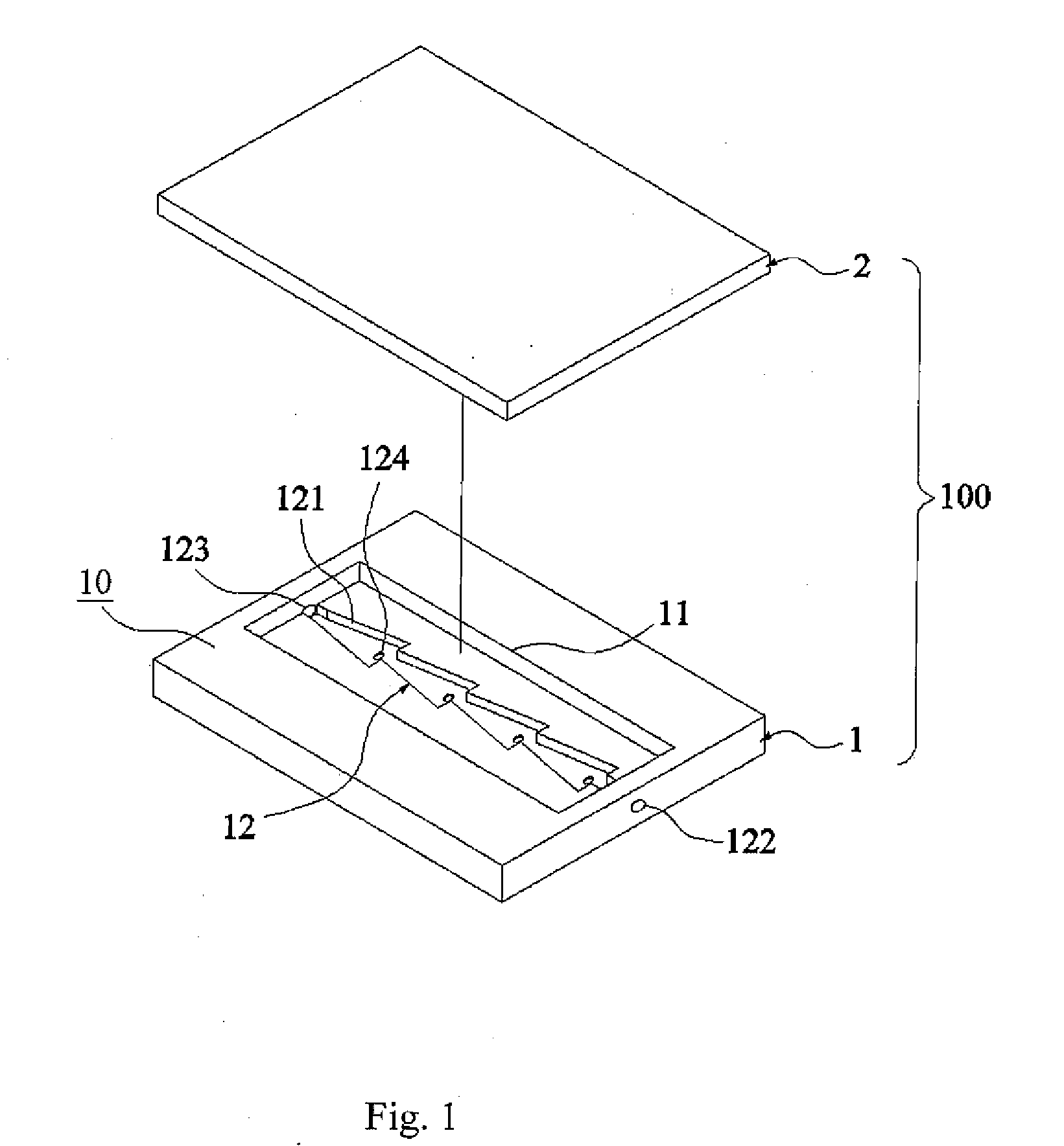
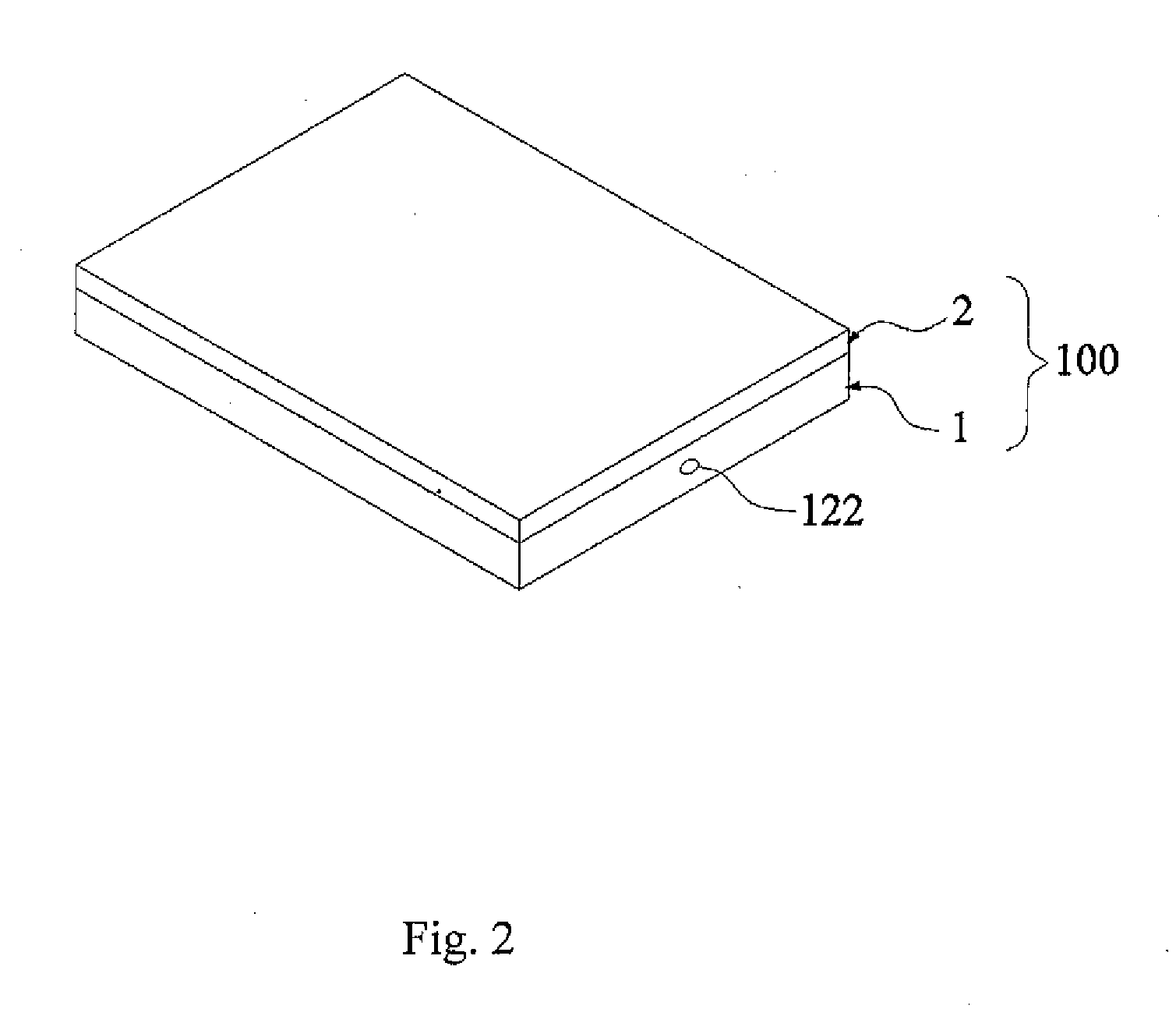
[0041]With reference to FIG. 1-FIG. 2, FIG. 1 is an exploded view showing the first embodiment of the present invention, and FIG. 2 is an assembly view corresponding to FIG. 1, In the first embodiment, microfluidic chip 100 is adapted to input and output a medium having a predetermined net flow speed so as to culture a tissue in vitro. As shown in figures, microfluidic chip 100 comprises a substrate 1 and a top cover 2. The substrate 1 is composed of polymethylmethacrylate (PMMA). The top cover 2 is adapted to cover the substrate 1.

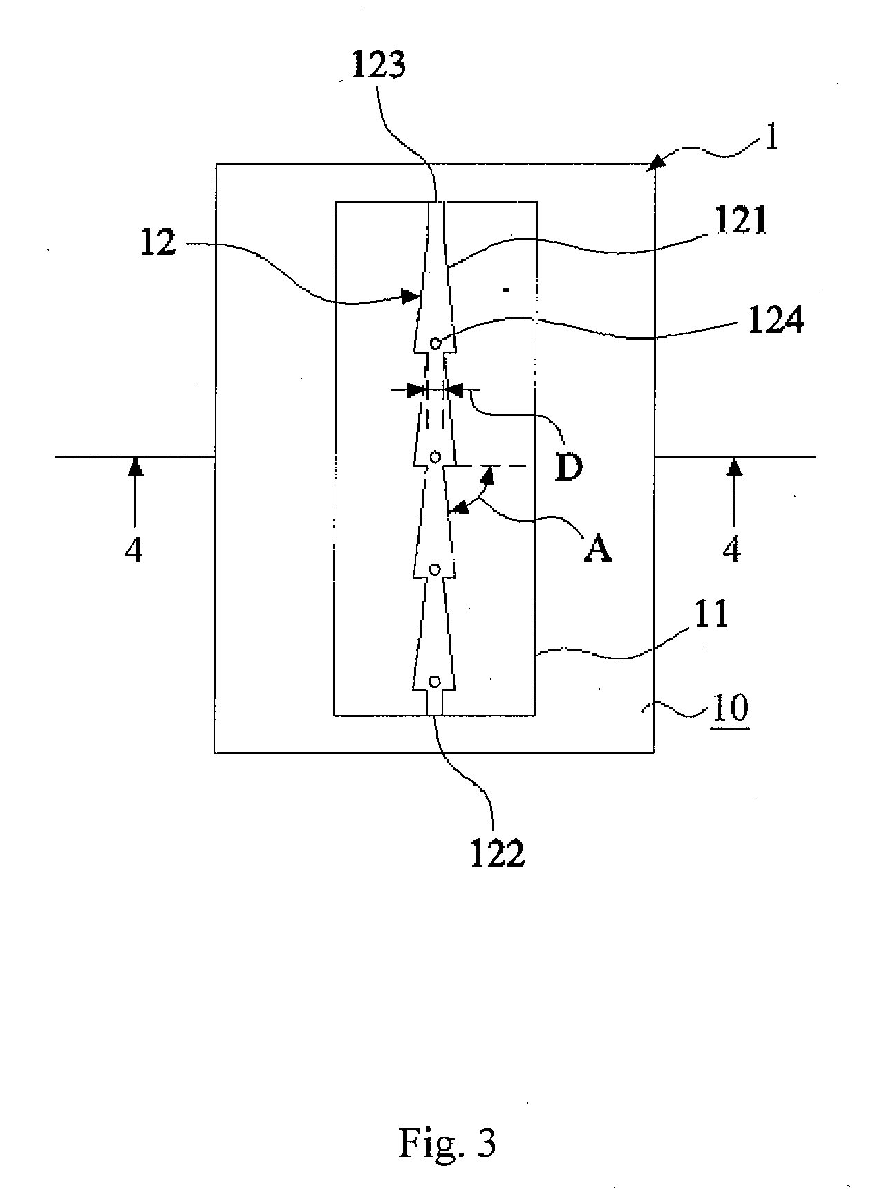
[0042]The substrate 1 has a surface 10, and a tissue culture area 11 is formed on the surface 10 of the substrate 1 (It is exemplified in this embodiment by, but not limits to, only one tissue culture area). The tissue culture area 11 has a microfluidic channel 12 formed by a plurality of connected geometrical structures 121 having a predetermined depth. The microfluidic channel 12 has an inlet 122 and an outlet 123 at two ends thereof for inputting the m...

embodiment 2

[0045]With reference to FIG. 5, which is a top view showing the substrate of the second embodiment of the present invention. In this embodiment, the substrate 1a has three tissue culture areas 11a, 11b and 11c, serially connected to form a one-dimensional array 14. The array 14 has an inlet 141 and an outlet 142 at two ends and two side channels 15a, 15b formed thereon. One end of side channels 15a is connected to inlet 141 of array 14, and the other end is connected to the section between tissue culture areas 11b and 11c. Similarly, one end of side channels 15b is connected to inlet 141 of array 14, and the other end is connected to the section between tissue culture areas 11a and 11b.

embodiment 3

[0046]With reference to FIG. 6 and FIGS. 7A-7F. FIG. 6 is a flow chart of the third embodiment of the present invention, and FIGS. 7A-7F are schematic views corresponding to the steps of FIG. 6. In this embodiment, a method for culturing tissue in vitro utilizing the foregoing microfluidic chip is provided. The method comprises the steps described as follow:

[0047]Step 101: Providing a polymer membrane 13 being cultured with a plurality of mesothelial cells C thereon. As shown in FIG. 7A, a plurality of mesothelial cells C are cultured on the polymer membrane 13 composed of PDMS. Clinical experiments indicate that mesothelial cells are capable of secreting some particular proteins which are helpful for culturing liver tissues. Based on this reason, mesothelial cells are cultured on the polymer membrane, so that the contact area between mesothelial cells and liver tissue can be increased, and the tissue may obtain more required proteins.

[0048]Step 102: Attaching the polymer membrane 1...


PUM

PropertyMeasurementUnit
angleaaaaaaaaaa
angleaaaaaaaaaa
angleaaaaaaaaaa

Abstract

Disclosed is a microfluidic chip and method using the same. The microfluidic chip comprises a substrate having a surface, and at least a tissue culture area formed on the surface of the substrate. The tissue culture area has a microfluidic channel formed by a plurality of connected geometrical structures (nozzle-type channels) having a predetermined depth. The microfluidic channel has an inlet and an outlet, which are at two ends of the microfluidic channel, for medium inputting and outputting, respectively. Additionally, at least an air-exchange hole is formed on the bottom of the microfluidic channel. By using the microfluidic chip for tissue culture, lateral flow speed and stress can be decreased, so as to prolong survival time of tissues (e.g. liver tissues).

Description

[0001]This claims the benefit of priority under 35 U.S.C. Sec. 119 from the prior Taiwan Patent Application No. 099107681, filed Mar. 16, 2010, the entire content of which is hereby incorporated by reference in its entireties.FIELD OF THE INVENTION[0002]The present invention relates to a device for tissue culture, particularly relates to a microfluidic chip and a method using the same.BACKGROUND OF THE INVENTION[0003]Since human body systems are complicated, once researchers desire to realize how drugs influence a human body, they often firstly experiment at cellular level. According to the experiment results including a series of changes in cell morphology and metabolism, they may predict the probable model of human reaction, and evaluate activity and toxicity of the drugs. If experiments can be more directly implemented in tissue to identify their activity and toxicity, the results should be more close to human researches.[0004]Traditional methods for culturing liver tissues inclu...

Claims


Application Information

Patent Timeline
Patent Type & Authority Applications(United States)
IPC IPC(8): C12N5/02C12M1/00
CPCB01L3/502715B01L2200/10B01L2300/0636C12M29/10B01L2300/10C12M23/16B01L2300/0816
Inventor WU, CHEN-WEILIU, CHENG-HSIENYEH, CHAU-TINGLIN, HUI-LINGLAI, HSIN-YUYU, TZU-CHI
Owner NATIONAL TSING HUA UNIVERSITY
Why Eureka
Try Eureka