This helps you quickly interpret patents by identifying the three key elements:
Problems solved by technology
Method used
Benefits of technology
Benefits of technology
[0026]According to the present invention, it is possible to effectively reduce the frequency of decoding failure in LDPC encoding / decoding.
Problems solved by technology
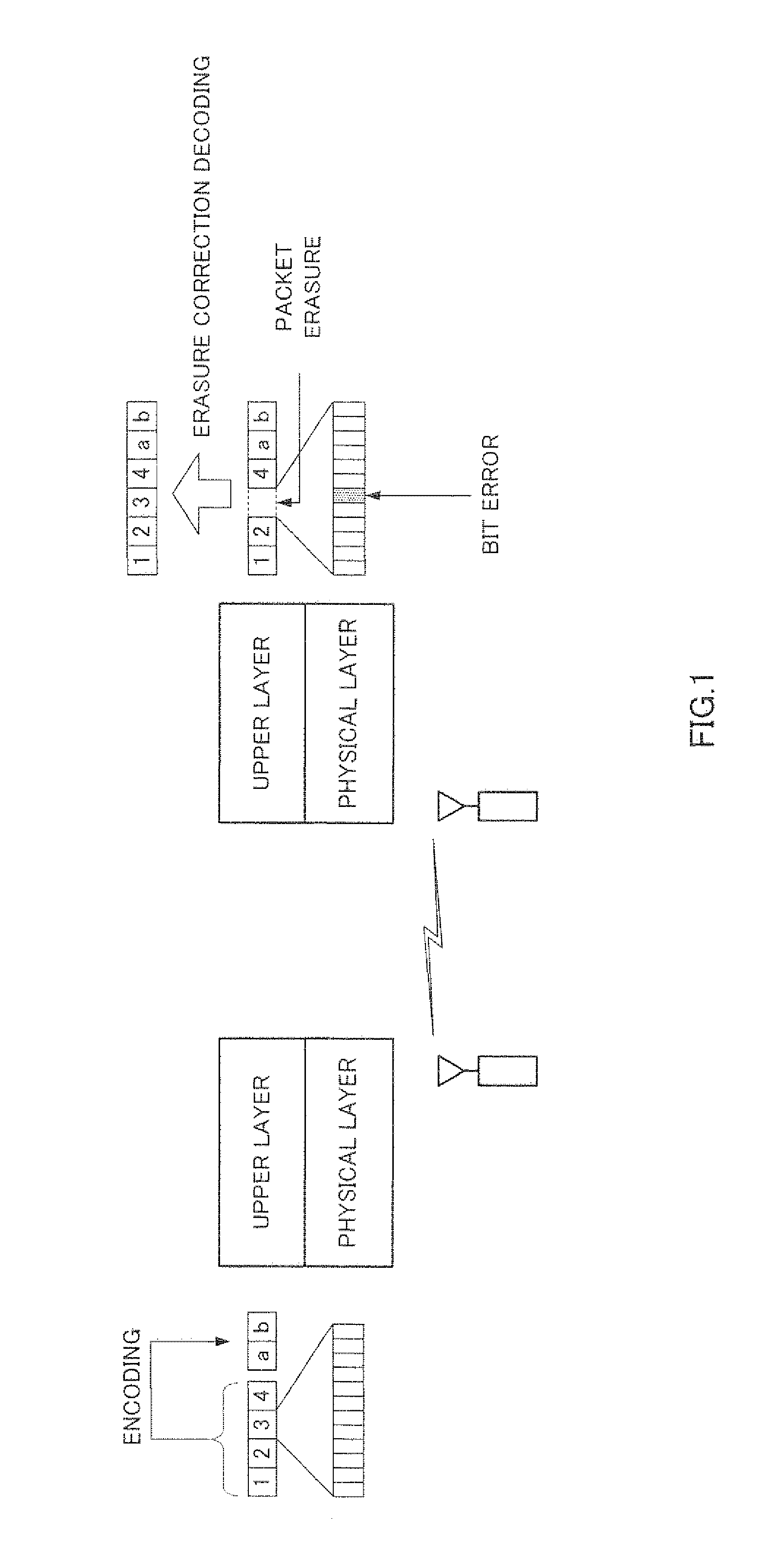
However, error correction is not effective in case where the amount of erasure is beyond correction performance of Reed-Solomon codes or in case where burst erasure occurs in which packets are lost continuously for a comparatively long period due to physical phenomena such as shadowing and fading that occur when a wirelesscommunication channel is used as the medium for performing packet communication.
In this case, although it is possible to improve correction performance by increasing a block length of Reed-Solomon code, there is a problem that the amount of operations in encoding / decoding processing and the circuit scale for these operations increase.
Method used
Image
Click on the blue label to locate the original text in one second.
Reading with bidirectional positioning of images and text.
Examples
embodiment 1
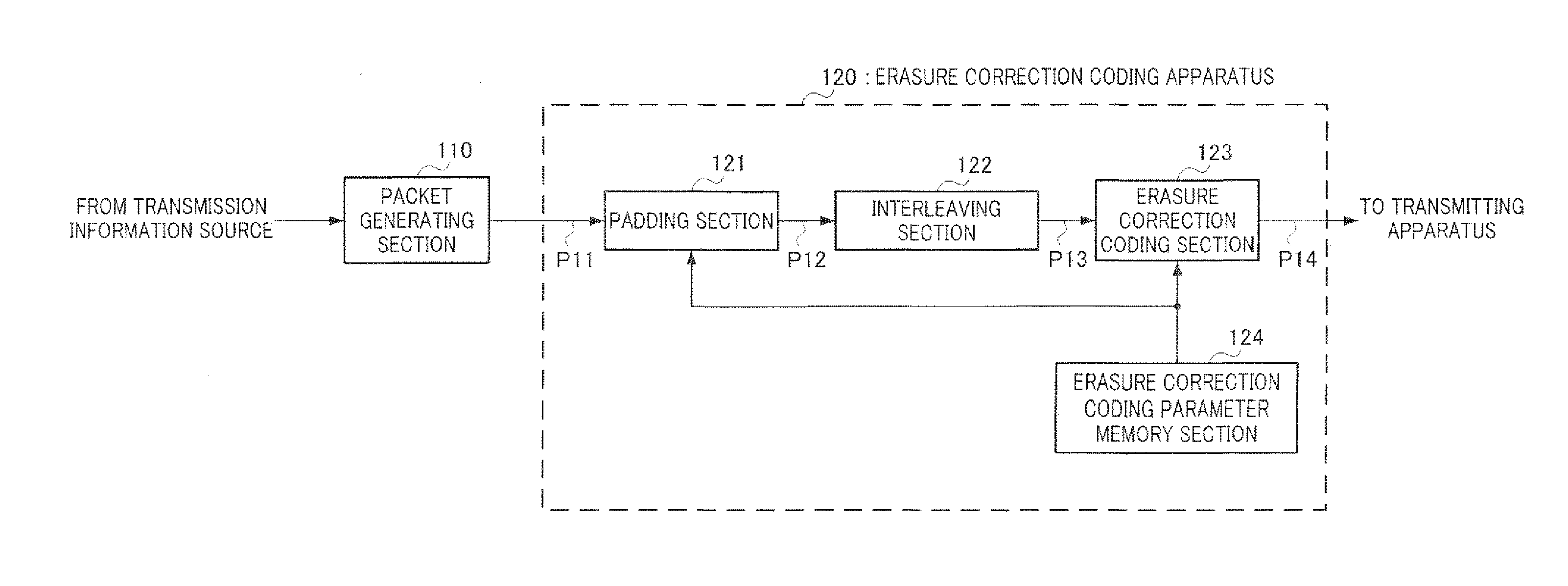
[0066]FIG. 5 shows an overall configuration of a communication system according to Embodiment 1 of the present embodiment. In FIG. 5, the communication system is formed with packet generating section 110, erasure correction coding apparatus 120, transmitting apparatus 130, communication channel 140, receiving apparatus 150, erasure correction decoding apparatus 160 and packet decoding section 170. In the same figure, packet generating section 110, erasure correction coding apparatus 120 and transmitting apparatus 130 are on the encoding side, and receiving apparatus 150, erasure correction decoding apparatus 160 and packet decoding section 170 are on the decoding side.
[0067]Packet generating section 110 adds a header to transmission information outputted from the transmission information source, and converts this information into information packets. For example, as shown in FIG. 6, to convert TSs (Transport Streams) of MPEG (Moving Picture Expert Group) given as transmission inform...
embodiment 2
[0148]Embodiment 2 of the present invention discloses a communication apparatus on the encoding side and a communication apparatus on a decoding side in a communication system that punctures and depunctures redundant packets to adjust the coding rate of a erasure correction code. Embodiment 2 differs from Embodiment 1 mainly in performing puncturing instead of padding, and applying interleavingprocessing after erasure correction coding processing.
[0149]FIG. 15 shows the configuration of main parts of the erasure correction coding apparatus according to Embodiment 2. Note that, in FIG. 15, the same components as in FIG. 7 will be assigned the same reference numerals and explanation thereof will be omitted. Erasure correction coding apparatus 220 of FIG. 15 is formed with erasure correction coding section 123, interleaving section 221, puncturing section 222 and erasure correction coding parameter memory section 124. Further, similar to Embodiment 1, a case will be explained below as...
embodiment 3
[0190]Embodiment 3 of the present invention discloses a case where the above configuration of providing the interleaving section between the erasure correction coding section and the puncturing section as disclosed in Embodiment 2, is applied to a communication apparatus that performs error correction coding per bit. Although a ease has been explained with Embodiment 2 where erasure correction coding, puncturing and interleaving are performed in packet units, erasure correction coding, puncturing and interleaving are performed in bit units with the present embodiment.
[0191]FIG. 25 shows a configuration example of a communication system according to Embodiment 3 of the present invention. Communication system 400 in FIG. 25 is formed with transmitting apparatus 500, communication channel 410 and receiving apparatus 600.
[0192]Transmitting apparatus 500 is formed with encoding section 510, modulating section 520 and transmitting section 530. Further, receiving apparatus 600 is formed wi...
PUM
Abstract
Disclosed are an encoding device and a decoding device which can effectively reduce the decoding failure frequency in LDPC encoding / decoding. A loss correction encoding device (120) includes a padding unit (121) which adds a padding packet to an information packet sequence; an interleave unit (122) which rearranges the padding packet and the information packet; and a loss correction encoding unit (123) which performs loss correction encoding for the packet string after the interleave. The interleave unit (122) rearranges the padding packet and the information packet according to variable nodes constituting a minimum stopping set of the inspection matrix which defines a low-density parity inspection code. The interleave unit (122) uses such a rearrangement pattern that avoids a loss correction failure by the minimum stopping set of the LDPC inspection matrix so as to reduce the probability of the loss correction failure by the minimum stopping set.
Description
TECHNICAL FIELD[0001]The present invention relates to an encoding apparatus and decoding apparatus that perform erasure correction of information data by adding redundancy to information data using, for example, low-density parity-check (“LDPC”) codes.BACKGROUND ART[0002]A system that performs communication based on packets using IP (Internet Protocol) generally uses a communication scheme for performing end-to-end retransmission control using TCP (Transport Control Protocol) in an upper protocol and a communication scheme for not performing retransmission control such as UDP (User Datagram Protocol), TCP is mainly employed when it is necessary to secure reliability in packet communication, for example, when text data such as a web page is transmitted and received or when a file is downloaded from a server. By contrast with this, UDP is employed when packet erasure is acceptable to some degree at the level of an application, for example, when streaming transmission of moving images ...
Claims
Application Information
Patent Timeline
Application Date:The date an application was filed.
Publication Date:The date a patent or application was officially published.
First Publication Date:The earliest publication date of a patent with the same application number.
Issue Date:Publication date of the patent grant document.
PCT Entry Date:The Entry date of PCT National Phase.
Estimated Expiry Date:The statutory expiry date of a patent right according to the Patent Law, and it is the longest term of protection that the patent right can achieve without the termination of the patent right due to other reasons(Term extension factor has been taken into account ).
Invalid Date:Actual expiry date is based on effective date or publication date of legal transaction data of invalid patent.

