Status indication method and status indication system

Inactive Publication Date: 2009-05-07
HITACHI GLOBAL STORAGE TECH NETHERLANDS BV
View PDF2 Cites 4 Cited by
  • Summary
  • Abstract
  • Description
  • Claims
  • Application Information

AI Technical Summary

Problems solved by technology

In mass-production manufacturing of home electronics, semiconductor devices, magnetic storage devices, printed circuit boards, etc., automated manufacturing systems such as robots and machine tools may perform manufacturing by treatment with chemical reaction, microfabrication, microassembly, or the like because it is difficult for workers to conduct operation directly.
In the above described manufacturing, raising productivity of the automated manufacturing system is an important challenge in view of investment recovery.
Especially, in the automated manufacturing system, there is an important challenge in reducing supplementary operation time including reducing failure frequency, setup operation time, waiting time for the works to stay until the works can be carried into the process, and the like.
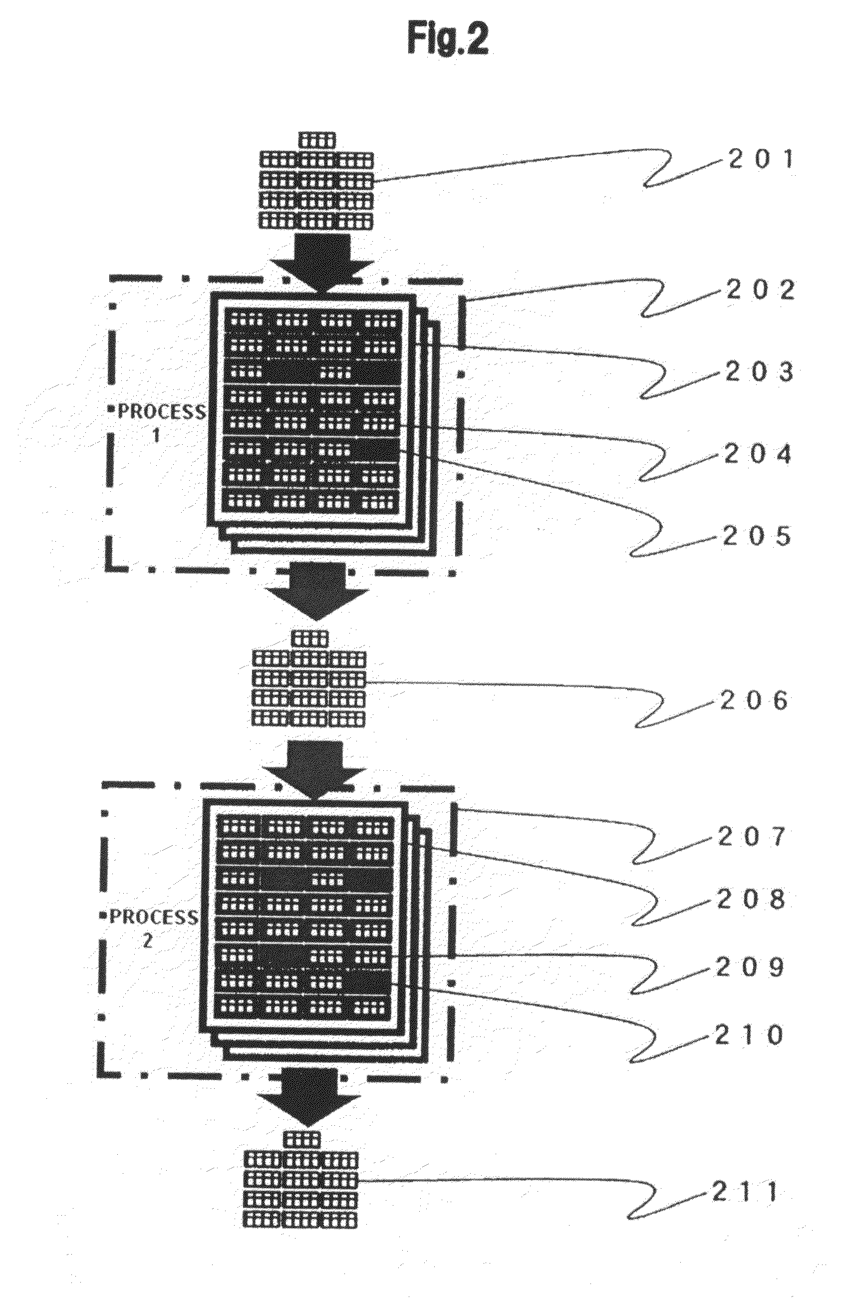
In this regard, there has been (1) a problem of magnetic storage device characteristics that even magnetic devices having the same capacity need different test times due to individual performance difference in reading and writing, and (2) an operation problem that the magnetic storage devices can not be carried out until the test of a predetermined amount or more of them relative to the entire number of magnetic storage devices have been finished.
Because of the problems (1) and (2), when workers should go to the testing device and conduct, operation is unpredictable and the magnetic storage devices wait for being carried out within the testing device after the test is finished, and therefore, there has been a problem that supplementary operation time becomes longer and the problem causes inhibition of improvement in productivity of the automated manufacturing system.
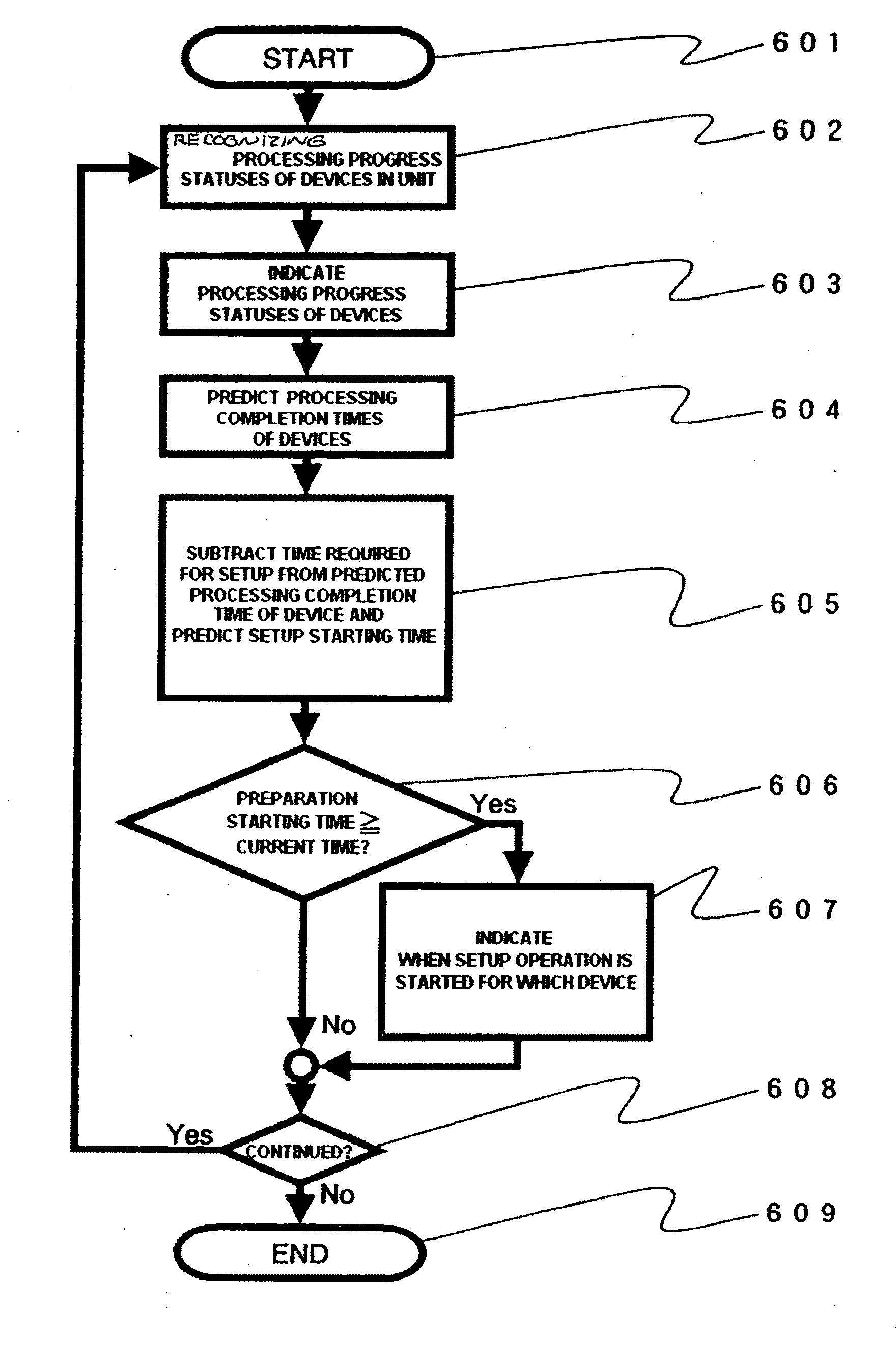
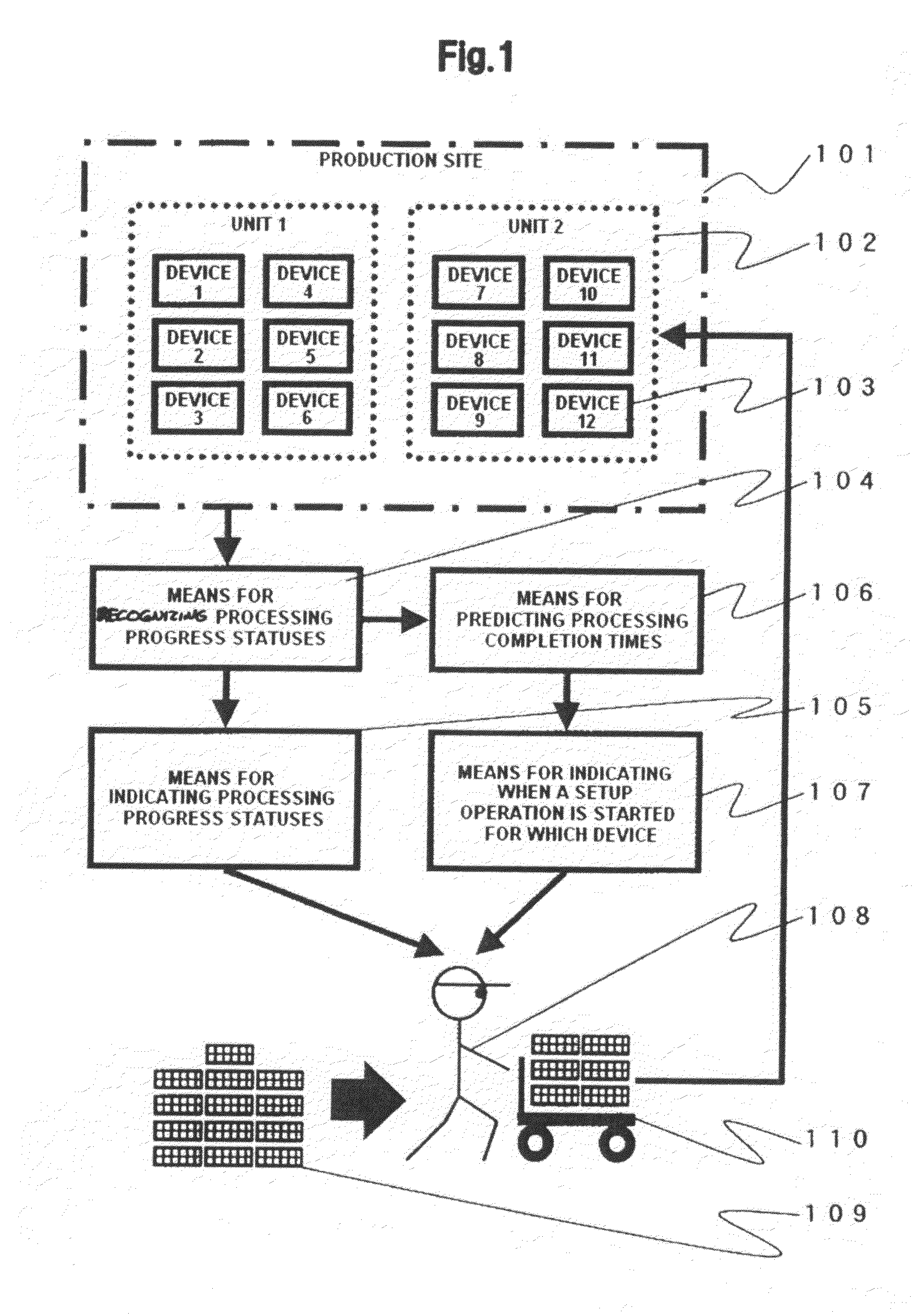
On the other hand, because of th

Method used


Image

  • Status indication method and status indication system
  • Status indication method and status indication system
  • Status indication method and status indication system

Examples


Embodiment Construction

[0025]Embodiments of the present invention provide a method and system for improvement in production efficiency for mass-production manufacturing of home electronics, semiconductor devices, magnetic storage devices, printed circuit boards, etc.

[0026]Embodiments of the invention are capable of raising productivity of an automated manufacturing system, focuses its attention on reduction of supplementary operation time, and provides a status indication technology of devices to solve (A) location designation problem to give specific instructions to workers as to where the device that has completed processing is in the production site, and (B) setup starting time designation problem to give instructions to workers when to conduct the setup for operation after a test is completed.

[0027]A representative status indication method of embodiments of the invention is a status indication method for managing a starting time of a setup operation in an automated manufacturing system in which setup ...


PUM


Abstract

Embodiments of the present invention provide a method and system for solving a location designation problem to give specific instructions to workers as to where the device that has completed processing is in the production site, and a setup starting time designation problem to give instructions to workers as to when the setup for operation after a test is completed is conducted. One embodiment includes a means for recognizing the processing progress statuses of the devices in the production site, means for indicating the processing progress statuses of the devices, means for predicting the processing completion times of the devices, and means for indicating when a preparation (setup operation) is started for a particular device. A worker receives the processing progress statuses of the respective devices of the respective units from the means for indicating the processing progress statuses of the devices, and records the time to carry in the works to be placed in the devices to the devices and start placement from the means for indicating when a setup operation is started for a particular device.

Description

CROSS-REFERENCE TO RELATED APPLICATION[0001]The instant nonprovisional patent application claims priority to Japanese Patent Application No. 2007-261116 filed Oct. 4, 2007 and which is incorporated by reference in its entirety herein for all purposes.BACKGROUND OF THE INVENTION[0002]In mass-production manufacturing of home electronics, semiconductor devices, magnetic storage devices, printed circuit boards, etc., automated manufacturing systems such as robots and machine tools may perform manufacturing by treatment with chemical reaction, microfabrication, microassembly, or the like because it is difficult for workers to conduct operation directly. In the automated manufacturing systems, robots and machine tools may conduct main operations and workers may conduct supplementary operations such as carrying in and carrying out of works and setup operations.[0003]For example, in manufacturing of magnetic storage devices, products are completed in the following manner: assembly operation...

Claims


Application Information

Patent Timeline
IPC IPC(8): G06F19/00G06Q10/00G05B19/418G06Q50/00G06Q50/04
CPCG06Q10/06G06Q30/0202G06Q10/0631
Inventor NAKAGAWA, TAKAHIROTSUYAMA, MASASHINISHIUCHI, SHIGETONONAKA, YOUICHI
Owner HITACHI GLOBAL STORAGE TECH NETHERLANDS BV
Why Eureka
Try Eureka