
Airplane tire with air pocket

a technology of air pockets and airframes, which is applied in the field of airframe tires, can solve the problems of repetitive fatigue, increased load, and enormous centrifugal force on the wheel of the airplane, and achieve the effects of reducing the shock applied, reducing the wear of the tire, and increasing the lifespan of the wheel

Inactive Publication Date: 2010-09-02
KIM SUNG BAE
View PDF8 Cites 11 Cited by
  • Summary
  • Abstract
  • Description
  • Claims
  • Application Information

AI Technical Summary

Benefits of technology

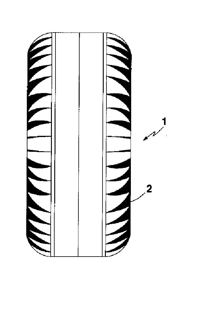
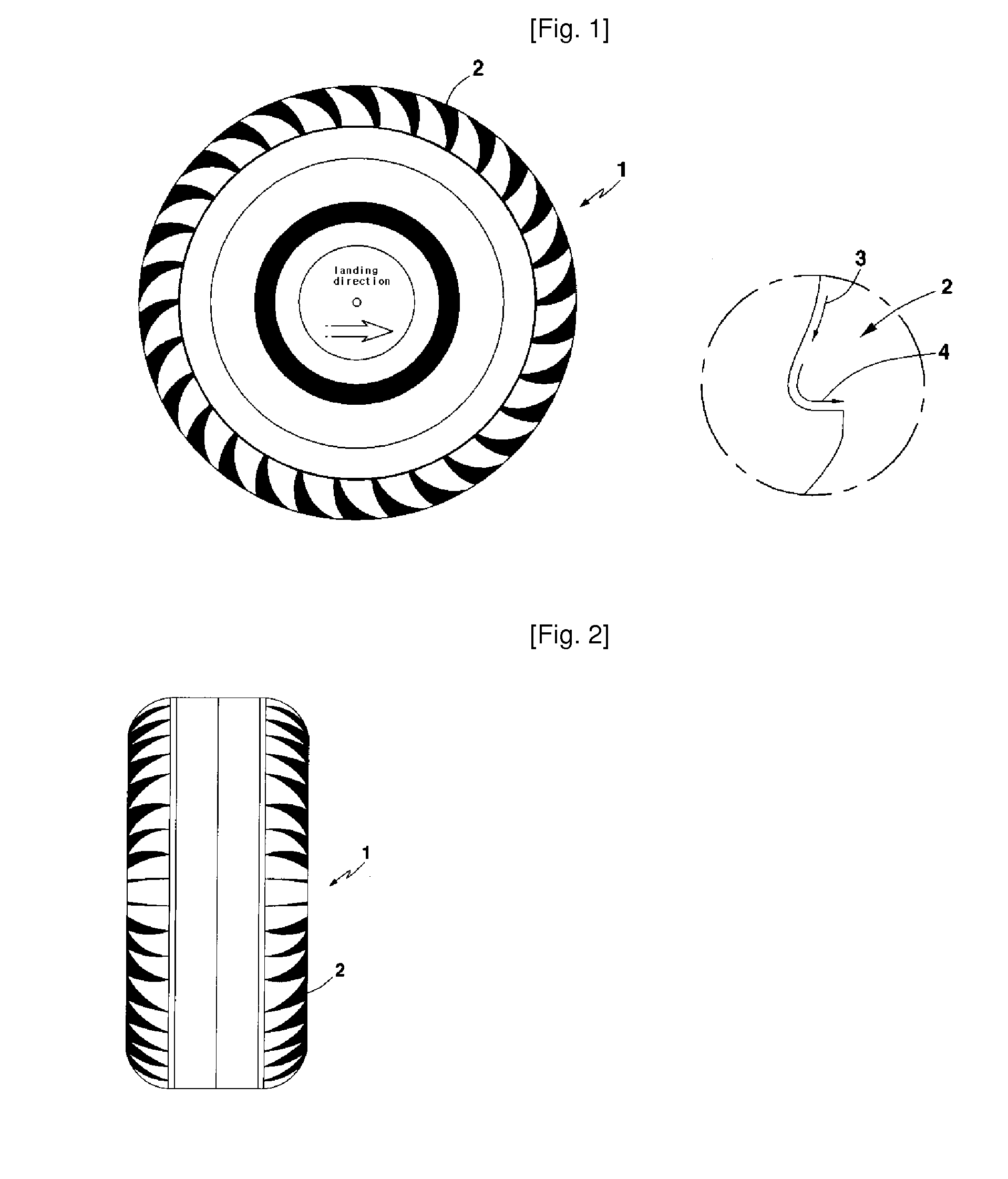
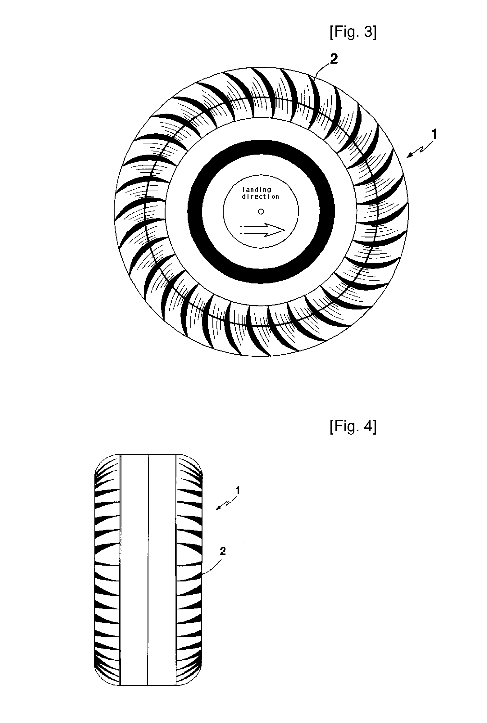
[0006]As described above, with the configuration of an airplane tire according to the present invention in which a plurality of rows of air pockets, each air pocket having a recess of a predetermined-depth, are formed at an outer circumferential surface of the airplane tire, it is possible to allow a wheel to rotate naturally in a landing direction by use of the resistance of air depending on the speed of an airplane. This has the effects of achieving a remarkable reduction in the shock applied to a tire upon landing and reducing the wear of the tire and guaranteeing the uniform wear of the tire, so as to increase the lifespan of the wheel. Also, according to the present invention, a damping distance can be shorten by virtue of an increased frictional force of the tire when an airplane body stops using a wheel brake and the tire can generate a sufficient centrifugal force via rotation thereof. This has the effect of contributing to the safe flying of an airplane, preventing environmental pollution via generation of a reduced amount of dust particles due to the friction and wear of the tire and improving the economic efficiency of the tire by virtue of the increased lifespan.

Problems solved by technology

Therefore, the wheel of the airplane is subjected to an enormous centrifugal force upon landing.
Since the airplane wheel is basically affected by a load due to a heavy airplane body, the centrifugal force disadvantageously acts to increase the load.
The increased wheel load causes a variation in the internal energy of the wheel (hereinafter, referred to as “tire”), resulting in repetitive fatigue and serious heat accumulation phenomenon.
The repetitive fatigue and heat accumulation phenomenon have a bad effect on physical properties of a material, thus causing deterioration of the physical properties.
Accordingly, rubber layers of a tire may suffer from separation or cracking.
Further, due to the fact that a conventional airplane wheel is in a stationary state at the time when a tire touches down on a landing strip, a face of the tire coming into contact with a landing strip has significant friction and wear.
If the tire is deformed by frictional heat, it causes a reduction in the lifespan of the tire and consequently, uneconomical frequent exchange of the tire.
Furthermore, dust particles generated by the friction and wear of the tire have a problem of environmental pollution of the surroundings.
Using a worn tire results in violent shaking of the airplane body, and in the worst case, may result in dangerous airplane accidents by the rupture of the tire.

Method used


Image

  • Airplane tire with air pocket
  • Airplane tire with air pocket
  • Airplane tire with air pocket

Examples


Embodiment Construction

[0018]Now, the configuration of the present invention will be described in detail with reference to the accompanying drawings.

[0019]FIGS. 1 and 2 are a side view and a front view illustrating an airplane wheel according to one embodiment of the present invention. FIGS. 3, 4, and 5 are a side view and front views illustrating an airplane wheel according to another embodiment of the present invention. FIG. 6 is a side view of a further embodiment of the present invention, illustrating a state in which a separate disc having air pockets radially formed therein is attached to a side surface of a conventional airplane tire. FIGS. 7 and 8 are a side view and a front view of a still further embodiment of the present invention, illustrating toothed air pockets are formed at an outer circumferential surface of a tire at opposite sides of an imaginary center line of the circumferential surface. FIGS. 9 and 10 are side views of other different embodiments of the present invention, illustrating...


PUM


Abstract

Disclosed is an airplane tire, and more particularly, is an airplane tire having air pockets, which can allow a tire wheel to rotate using the resistance of air depending on the speed of an airplane upon landing. The airplane tire can alleviate the landing shock of the tire and preventing wear and deformation of the tire by friction. In particular, the airplane tire can shorten a damping distance by virtue of an increased frictional force thereof when an airplane body stops using a tire wheel brake and achieve generation of a sufficient centrifugal force by rotation, thereby contributing to the safe flying of an airplane and the elimination of environmental pollution.

Description

TECHNICAL FIELD[0001]The present invention relates to an airplane tire, and more particularly, to an airplane tire having air pockets, which can allow a tire wheel to rotate using the resistance of air depending on the speed of an airplane upon landing, thereby alleviating the landing shock of the tire against the ground and preventing wear and deformation of the tire by frictional heat, and in particular, which can shorten a damping distance by virtue of an increased frictional force thereof when an airplane body stops using a tire wheel brake and achieve generation of a sufficient centrifugal force by rotation, thereby contributing to the safe flying of an airplane.BACKGROUND ART[0002]In general, an airplane wheel is the most important airplane component in charge of takeoff and landing of an airplane. The wheel and associated peripheral devices are collectively called as a landing gear. To reduce the resistance of air, most airplanes try to fold the landing gear immediately on ta...

Claims


Application Information

Patent Timeline
Patent Type & Authority Applications(United States)
IPC IPC(8): B60C11/03
CPCB60C11/00B60C13/02B60C11/01B60C11/03B60C9/00
Inventor KIM, SUNG BAE
Owner KIM SUNG BAE
Learn More