
Heat transferable material for improved image stability

Active Publication Date: 2010-09-02
KODAK ALARIS INC
View PDF12 Cites 22 Cited by
  • Summary
  • Abstract
  • Description
  • Claims
  • Application Information

AI Technical Summary

Benefits of technology

[0016]The heat transferable donor element of this invention containing a transferable polymeric binder and a transferable N-oxyl radical light stabilizer provides the advantages of reducing light fade, reducing iridescence, and lowering costs for image production by reducing or eliminating the need for UV absorbing materials. Other advantages will be apparent upon review of this document in full.

Problems solved by technology

Also known is that all such images are susceptible to environmental factors, particularly light fade.
Thermal, inkjet, and electrophotographic images also can suffer from iridescence problems, which are unsightly to the viewer.
Thermal, ink jet, and electrophotographic prints are susceptible to retransfer of colorants to adjacent surfaces and to discoloration by fingerprints because the colorants remain at the surface of the receiver.
The most common approach is to filter out UV radiation since it is known that UV radiation is detrimental to the underlying colorants.
This approach has practical limitations on the amount of UV radiation that can be absorbed because there is a practical limitation on the thickness of the protective overcoat as well as the concentration of the UV absorbing dye that can be applied.
The overcoat provides inferior gloss and iridescence performance due to refractive index mismatch with the dye receiving layer.
Although the particles reduce the iridescence problems, the particles lower the gloss of the imaged print.
U.S. Pat. No. 5,670,449 discloses the use of elastomeric beads in a protective overcoat for better raw-stock keeping, but the gloss performance of these protective overcoats is not optimum.
The inorganic particles, e.g. silica, are required to provide smooth protective overcoat tear-off, but these degrade gloss and are detrimental to the gravure coating quality.
The gloss improvement provided is not adequate.

Method used


Image

  • Heat transferable material for improved image stability
  • Heat transferable material for improved image stability
  • Heat transferable material for improved image stability

Examples


embodiment 1

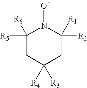
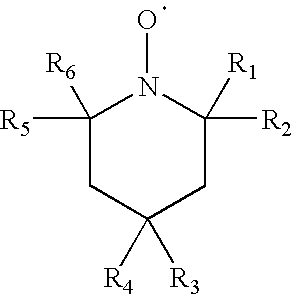
[0077]A heat transferable donor element comprising a polymeric support, the support having at least one portion thereof coated with a heat transferable material comprising a heat transferable polymeric binder and a light stabilizer that is an N-oxyl radical that is derived from a hindered amine, the N-oxyl radical having the following formula:

wherein R1, R2, R5, and R6 are each independently selected from a straight or branched C1-C6 alkyl or alkene, and R3 and R4 are each independently selected from H, OH, OR, COOH, or COOR, wherein R is a straight or branched C1-C6 alkyl or alkene, and having a molecular weight of 600 or less.

embodiment 2

[0078]The element of embodiment 1 comprising at least one protective overcoat patch.

embodiment 3

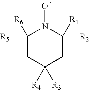
[0079]The element of embodiment 1 or 2 wherein the N-oxyl radical light stabilizer is:


PUM

PropertyMeasurementUnit
Fractionaaaaaaaaaa
Fractionaaaaaaaaaa
Fractionaaaaaaaaaa

Abstract

A heat transferable material includes a heat transferable polymeric binder and a light stabilizer that is an N-oxyl radical derived from a hindered amine, the N-oxyl radical having the following formula,wherein R1, R2, R5, and R6 are each independently selected from a straight or branched C1-C6 alkyl, and R3 and R4 are each independently selected from H, OH, OR, COOH, or COOR, wherein R is a straight or branched C1-C6 alkyl or alkene, and having a molecular weight of 600 or less, is described. The heat transferable material can be in one or more sections or patches on a thermal donor element to provide a protective overcoat material. Optionally, a patch in the donor element can also include a dye. The heat transferable material provides better image stability and improved iridescence when applied to a thermal, inkjet, electophotographic, or silver halide receiver.

Description

CROSS-REFERENCE TO RELATED APPLICATIONS[0001]This application is a Continuation-in-part of U.S. Ser. No. 12 / 436,833 that was filed on May 7, 2009, and reference is also made to and priority claimed from U.S. Provisional Application Ser. No. 61 / 156,605, filed Mar. 2, 2009.FIELD OF THE INVENTION[0002]The present invention relates to a heat transferable material including a heat transferable polymeric binder and an N-oxyl radical that is derived from a hindered amine, and that behaves as a light stabilizer that provides improved image stability and reduced iridescence when applied to a receiver.BACKGROUND OF THE INVENTION[0003]There are many ways of forming an image. Images can be formed through thermal transfer of dyes, inkjet applications, electrophotographic reproduction, and silver halide image development. Also known is that all such images are susceptible to environmental factors, particularly light fade. Thermal, inkjet, and electrophotographic images also can suffer from irides...

Claims


Application Information

Patent Timeline
IPC IPC(8): B44C1/17B41M5/382B41M5/50C08K5/3435
CPCB41M5/392B41M5/423B41M2205/40B41M2205/06B41M7/0027B41M2205/30B41M5/38264
Inventor VREELAND, WILLIAM B.
Owner KODAK ALARIS INC
Learn More