System for inductive power provision in wet environments

a technology of inductive power and wet environment, applied in the direction of transformers/inductance circuits, transformers, electrical apparatus, etc., can solve the problems of inability to know the future function of the room, difficult to relocate power outlets, time-consuming and unsightly, etc., and achieve the effect of improving the flux guidan

Active Publication Date: 2010-09-02
POWERMAT TECHNOLOGIES
View PDF99 Cites 102 Cited by
  • Summary
  • Abstract
  • Description
  • Claims
  • Application Information

AI Technical Summary

Benefits of technology

[0043]the tape comprising a ferromagnetic core for improving flux guidance between the primary inductor and the secondary inductor.

Problems solved by technology

Often, however, the future function of the room is not known during its construction.
Consequently, it is often necessary to relocate power outlets long after a building is completed, which can be costly.
Once the wall has been finished, the relocation of power outlets is difficult.
It will be appreciated that this solution is costly, time consuming and unsightly.
Furthermore, the utility outlet once connected cannot be removed without exposing the bared conductor.
Aside from being unsightly, if the protruding sockets are knocked they may become detached from the wall.
Because the sockets and wires are supported only by the adhesive and not by additional fasteners, if the sockets become detached from the wall they will only be supported by the wire itself, thereby posing a safety hazard.
Nevertheless, children do occasionally manage to insert pencils, pins and other objects into socket holes, sometimes with fatal results.
Water can also cause shorting and may result in electrocution.
Since sockets are unsightly, the number of sockets installed on a wall is generally limited.
Often, their position is not appropriate to changing requirements and extension leads are needed.

Method used


Image

  • System for inductive power provision in wet environments
  • System for inductive power provision in wet environments
  • System for inductive power provision in wet environments

Examples


first embodiment

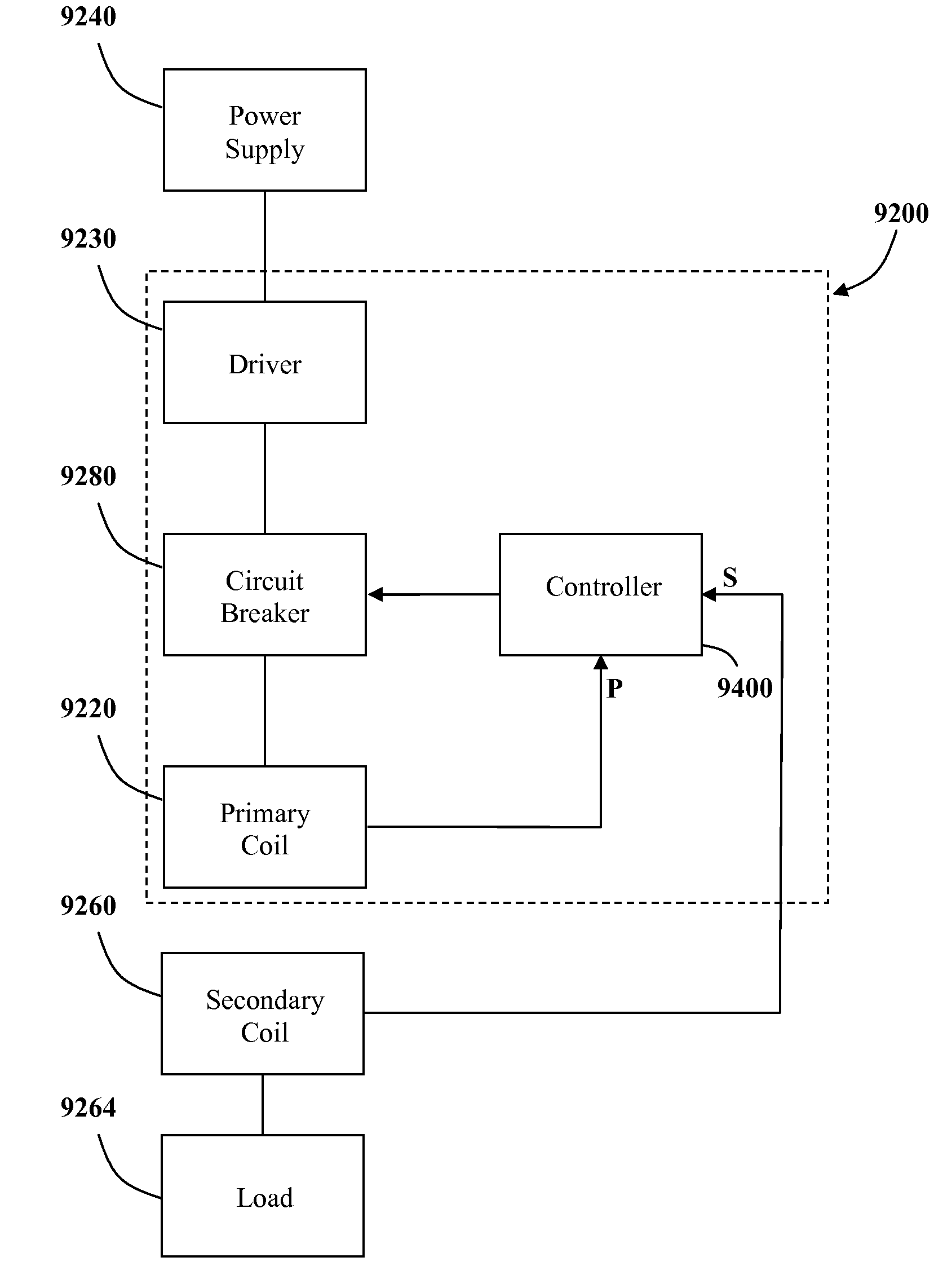
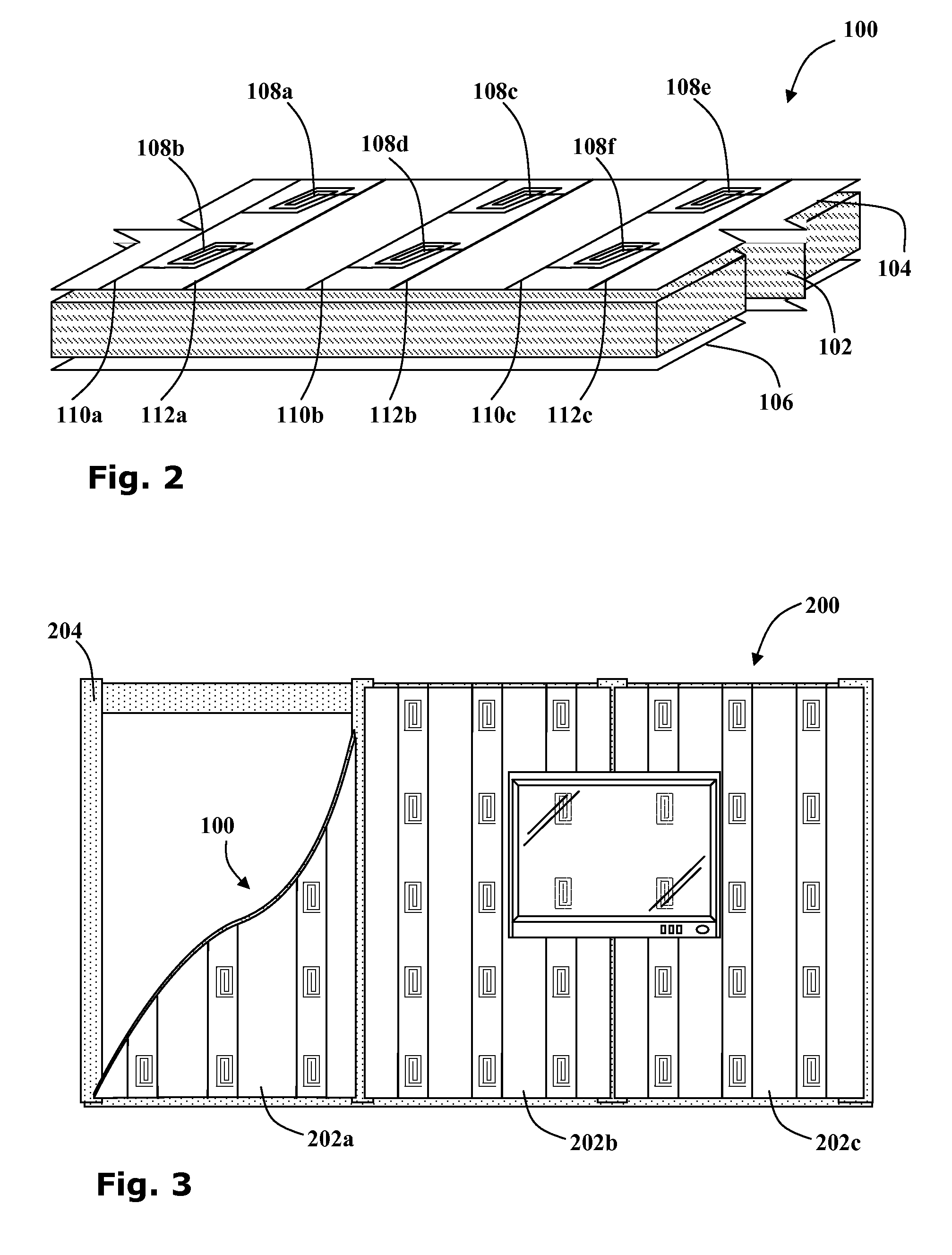
[0162]Two embodiments of the power outlet tape are shown in FIGS. 10a and 10b. Referring particularly to FIG. 10a, in the first embodiment, the electrical components 840 are configured such that a common electrical conducting strip 844 connects with all the primary inductive coils 842 along the tape. Such a control strip 846 may consist of a bundle of conducting wires each of which is connected to only one of the primary inductive coils 842.

[0163]A segment of the power outlet tape is detached from the roll, by severing the tape, perhaps by manual tearing or by using a cutting implement such as a pair of scissors or a knife. Wherever the power outlet tape is severed, the common electrical conducting strip 844 and the control strip 846 may be connected to a control box 500. With this first configuration, the control strip 846 may be used to selectively activate each primary inductive coil 842.

[0164]A second embodiment of the electrical components 640 of the power outlet tape is shown ...

second embodiment

[0211]In the positioning mechanism 5160, as shown in FIG. 15a, a primary coil unit 5120 is slidably mounted to a rail 5162. The rail 5162 may run horizontally behind the skirting board 5141 of a wall 5140 for example. The primary coil unit 5120 is configured to be movable into various positions along the rail 5162. The primary coil unit 5120 may be pulled manually by magnets as in the embodiment of FIG. 15a. Alternatively the primary coil unit 5120 may be mounted upon motorized wheels 5164 and configured to drive itself along the rail 5162.

[0212]It will be appreciated that the rail 5162 may be straight or curved and may even snake back and forth to cover an extended area of the wall 5140, as shown in FIG. 15b. According to still other embodiments, more than one primary coil units 5120b may be independently positionable. Alternatively a plurality of primary coil units may all be moved together.

third embodiment

[0213]Reference is now made to FIG. 15c showing the positioning mechanism 5160c in which a primary coil unit 5120 is slidably mounted to a boom rail 5162, which is slidably supported by a pair of generally perpendicular supporting tracks 5164 to form an adjustable H frame 5165. Thus the position of the primary coil unit 5120 may be moved behind a surface layer 5140.

[0214]It will be appreciated that in embodiments where the positioning mechanism 5160 is orientated vertically, behind a vertical surface layer 5140 such as a wall say, the supporting tracks 5164 may be replaced by supporting pulleys. Such pulleys may be used to support the boom rail 5162 which may be lowered and raised by adjusting the pulleys either manually or by a driving motor. Alternatively, the primary coil unit 5120 may be suspended from a pulley mounted to trolley configured to run horizontally along a fixed gantry beam spanning the width of the wall.


PUM


Abstract

Inductive power providing systems suitable for wet environments are disclosed. Water resistant inductive outlets include primary inductors incorporated into water resistant work-surfaces. Water resistant inductive power receivers include secondary inductors incorporated into water resistant casings. Secondary inductors are configured to couple with primary inductors thereby providing power to electrical loads connected thereto.

Description

CROSS-REFERENCE TO RELATED APPLICATIONS[0001]This application is a continuation-in-part of PCT application Serial No. PCT / IL2008 / 001347 filed Oct. 12, 2008, which claims the benefit of U.S. provisional application Ser. Nos. 60 / 960,636 filed Oct. 9, 2007; 60 / 001,106 filed Oct. 31, 2007; 60 / 996,460 filed Nov. 19, 2007; 60 / 996,592 filed Nov. 27, 2007; 60 / 996,922 filed Dec. 11, 2007; 61 / 006,037 filed Dec. 17, 2007; 61 / 008,319 filed Dec. 20, 2007; 61 / 006,132 filed Dec. 26, 2007; 61 / 006,238 filed Jan. 2, 2008 and 61 / 193,456 filed Dec. 2, 2008, which are hereby incorporated by reference in their entirety.BACKGROUND OF THE INVENTION[0002]1. Field of the Invention[0003]Embodiments of the present invention relate to providing inductive power in wet environments. In particular selected embodiments relate to inductive power outlets incorporated into water resistant work-tops and inductive power receivers incorporated into water resistant electrical devices.[0004]2. Background Art[0005]The provi...

Claims


Application Information

Patent Timeline
Patent Type & Authority Applications(United States)
IPC IPC(8): H02J17/00
CPCH02J5/005H02J50/402H02J50/90H02J50/70H02J50/10H02J50/80
Inventor AZANCOT, YOSSIBEN-SHALOM, AMIRGREENWALD, OOLAROFE, ARIK
Owner POWERMAT TECHNOLOGIES
Why Eureka
Try Eureka