Method and apparatus for determining a field current in brushless electrical machines

a field current and brushless technology, applied in the direction of motor/generator/converter stopper, electric generator control, dynamo-electric converter control, etc., can solve the problem of high computational complexity of the evaluation of the field current determination

Inactive Publication Date: 2010-09-02
ABB (SCHWEIZ) AG
View PDF5 Cites 6 Cited by
  • Summary
  • Abstract
  • Description
  • Claims
  • Application Information

AI Technical Summary

Benefits of technology

[0008]An apparatus is also disclosed for determining a field current through a field winding in an electrical machine having a stator, a rotor, and a field-circuit transformer for producing, by induction of an electrical current on a rotor side, the field current with which the field winding is energized to generate an excitation magnetic field, the apparatus comprising: a device for driving a primary of a field-circuit transformer to produce a field current in a rotor which is derived from current induced on a secondary of the field-circuit transformer; a current detection unit for measuring at least one phase current in at least one primary-side phase of the field-circuit transformer; a maximum current determination unit for determining a maximum value of the at least one measured phase current; and a motor control unit for determining the field current through the field winding based on the maximum value determined.
[0009]A motor system is also disclosed, comprising an electrical machine with a stator, and a rotor which has a field winding; a field-circuit transformer for producing by induction of an electrical current on a rotor side, field current with which a field winding generates an excitation magnetic field; a device for driving a primary of the field-circuit transformer to produce the field current in the rotor which is derived from current induced on a secondary of the field-circuit transformer; a current detection unit for measuring at least one phase current in at least one primary-side phase of the field-circuit transformer; a maximum current determination unit for determining a maximum value of the at least measured phase current; and a motor control unit for determining the field current through the field winding based on the maximum value determined.

Problems solved by technology

Since the electrical machine does not have a tap for currents on the rotor side and does not permit reliable current measurement in any other way, the field current is estimated by measurements of electrical variables on the stator side.
The output voltage of the actuating element is additionally a non-sinusoidal voltage, as a result of which the computation complexity in the evaluation for the determination of the field current can be high.

Method used


Image

  • Method and apparatus for determining a field current in brushless electrical machines
  • Method and apparatus for determining a field current in brushless electrical machines
  • Method and apparatus for determining a field current in brushless electrical machines

Examples


Embodiment Construction

[0016]A method and an apparatus are disclosed with which a field current can be determined in a precise and reliable manner using measurement of an electrical variable measured on the stator side.

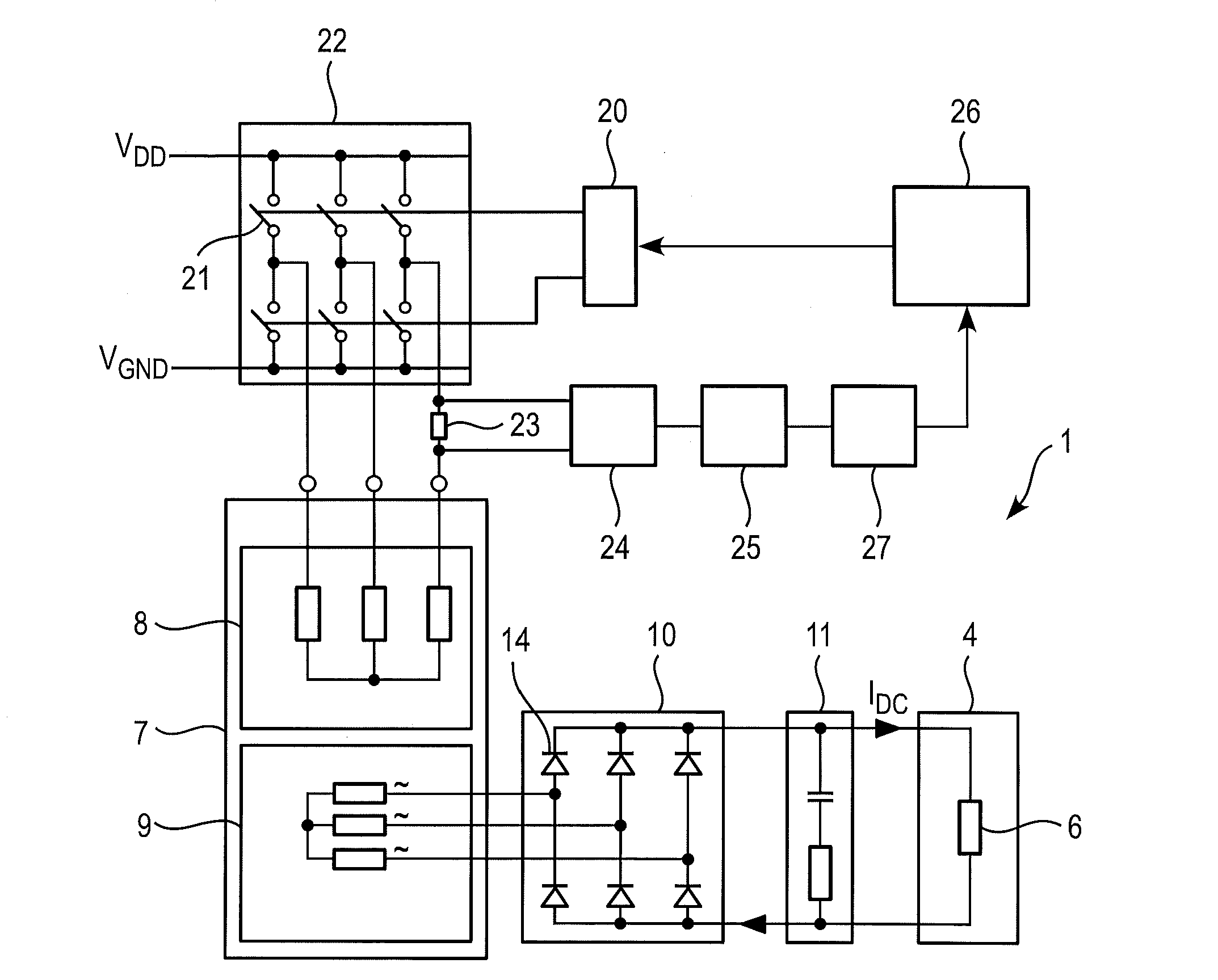
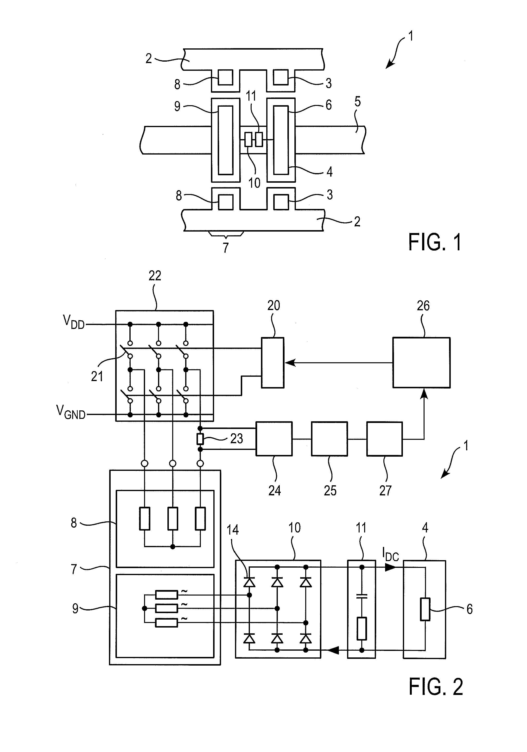
[0017]In accordance with a first exemplary embodiment, a method is disclosed for determining a field current through a field winding in an electrical machine with a stator and a rotor. The electrical machine includes a field-circuit transformer in order to bring about, by induction of an electrical current on the rotor side, the field current with which a field winding is energized in order to generate an excitation magnetic field. An exemplary method includes:

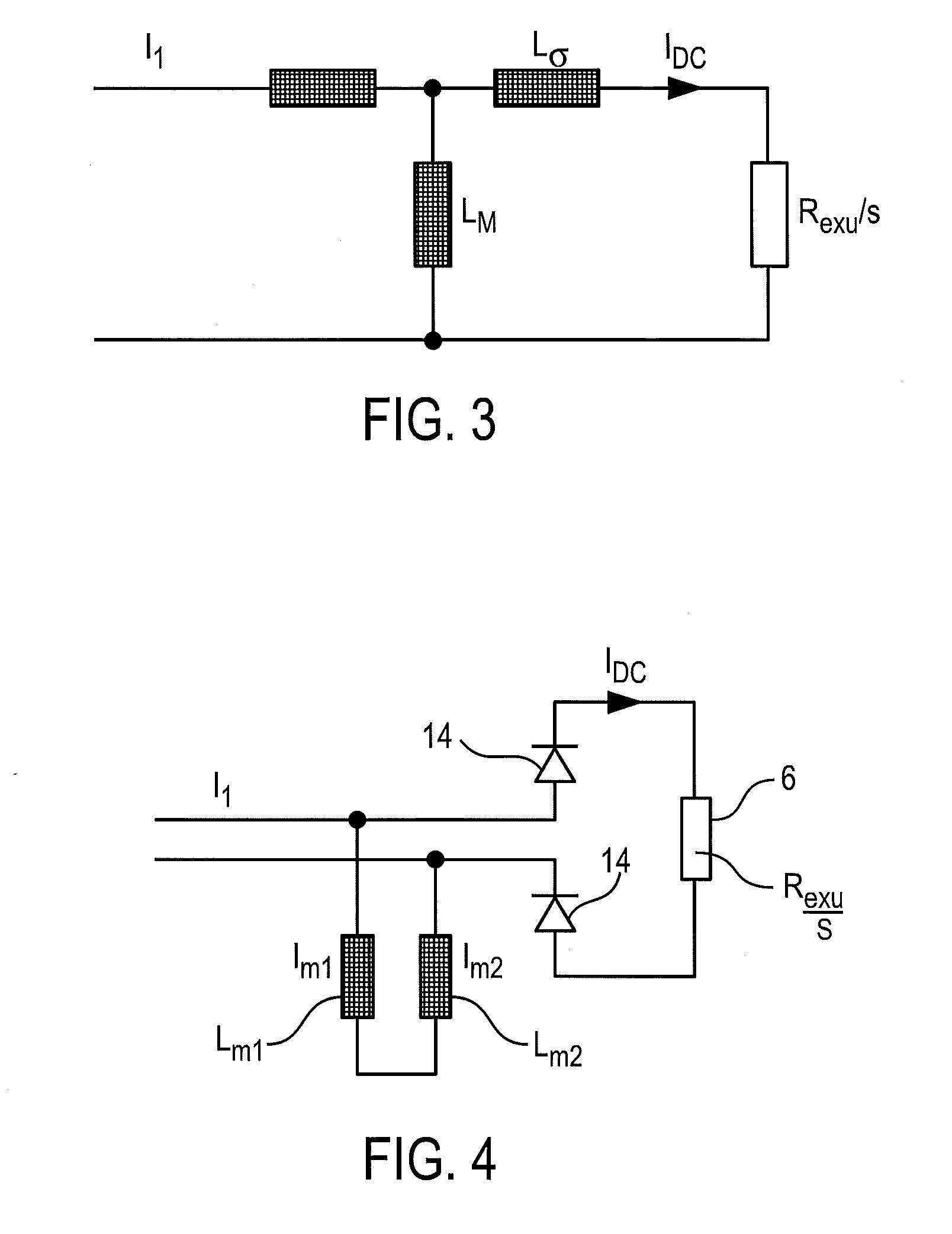
[0018]primary-side driving of the field-circuit transformer in order to bring about a field current in the rotor, which is derived from the current induced on the secondary side in the field-circuit transformer;

[0019]measurement of one or more primary-side phase currents in the field-circuit transformer;

[0020]determination of a maximu...


PUM


Abstract

A method and an apparatus are described for determining a field current through a field winding in an electrical machine with a stator and a rotor. The electrical machine includes a field-circuit transformer to produce, by induction of an electrical current on the rotor side, field current with which a field winding is energized in order to generate an excitation magnetic field. The method includes driving the primary side of the field-circuit transformer to produce a field current in the rotor, which is derived from the current induced on the secondary side in the field-circuit transformer; measuring one or more phase currents in one or more primary-side phases of the field-circuit transformer; determining a maximum value depending on the one or more measured phase currents; determining the field current through the field winding depending on the determined maximum value.

Description

RELATED APPLICATION[0001]This application is a continuation application under 35 U.S.C. §120 of PCT / EP2008 / 060746 filed as an International Application on Aug. 15, 2008 designating the U.S., which claims the benefit under 35 U.S.C. §119 of U.S. Provisional Patent No. 60 / 971,406 filed on Sep. 11, 2007, the entire contents of which are hereby incorporated by reference in their entireties.FIELD[0002]The disclosure relates to brushless electrical machines with field windings and methods for operating such machines.BACKGROUND INFORMATION[0003]Brushless electrical machines such as, for example, synchronous motors can have, in addition to a stator winding, a field winding arranged on the rotor. The field winding is supplied with electrical energy to generate an excitation magnetic field. The electrical energy is provided to the field winding by virtue of transformer coupling between one or more primary coils on the stator and one or more secondary coils on the rotor. The field-circuit tran...

Claims


Application Information

Patent Timeline
Patent Type & Authority Applications(United States)
IPC IPC(8): H02P23/00
CPCH02P9/14H02P9/302H02P2205/05H02P2205/01H02P25/021H02P25/024
Inventor ECKERLE, JOHN
Owner ABB (SCHWEIZ) AG
Why Eureka
Try Eureka