Image input device, image input-output device and electronic unit

a technology of image input and output device, applied in the direction of instruments, computing, electric digital data processing, etc., can solve the problems of false signal generation, deterioration of detection accuracy, so as to achieve the effect of more accuracy

Inactive Publication Date: 2010-09-02
JAPAN DISPLAY WEST
View PDF5 Cites 36 Cited by
  • Summary
  • Abstract
  • Description
  • Claims
  • Application Information

AI Technical Summary

Benefits of technology

[0015]According to the image input device, image I / O device and electronic unit, the light source or display panel alternates between the ON period and the OFF period so that the ON period is set shorter than the OFF period, and the reading by the first photo-detection element is performed in each period after a mutually-same light receiving time has passed. The image processing section generates a difference image from an ON image obtained in the ON period and an OFF image obtained in an OFF period each based on the outputs from the first photo-detection element, and carries out data processing based on the difference image. In this manner, the first photo-detection element is less likely to be saturated even when external light level is strong, and generation of a false signal is suppressed even when an object is moving or the external light level is not constant. Accordingly, information on the position, shape or size of a proximity object is available with more accuracy irrespective of usage conditions.

Problems solved by technology

However, the above disclosures have issues in that, when the external light level (external light illumination) is strong, photosensor may become saturated or the light turns around to the rear side of the object to be detected, and such saturation of photosensor and leakage of external light may deteriorate accuracy in detecting the reflection light.
Moreover, in the disclosure of JP2006-276223A, since there is a time lag between the light-ON period and the light-OFF period caused by the time division control, when an object to be detected is moving, a false signal may be generated because of the time lag, and accuracy of detection may be thereby deteriorated.
Further, such false signal may also be generated when the external light level has been changed because of the time lag.

Method used


Image

  • Image input device, image input-output device and electronic unit
  • Image input device, image input-output device and electronic unit
  • Image input device, image input-output device and electronic unit

Examples


embodiment

[Entire Configuration of Image I / O Device 1]

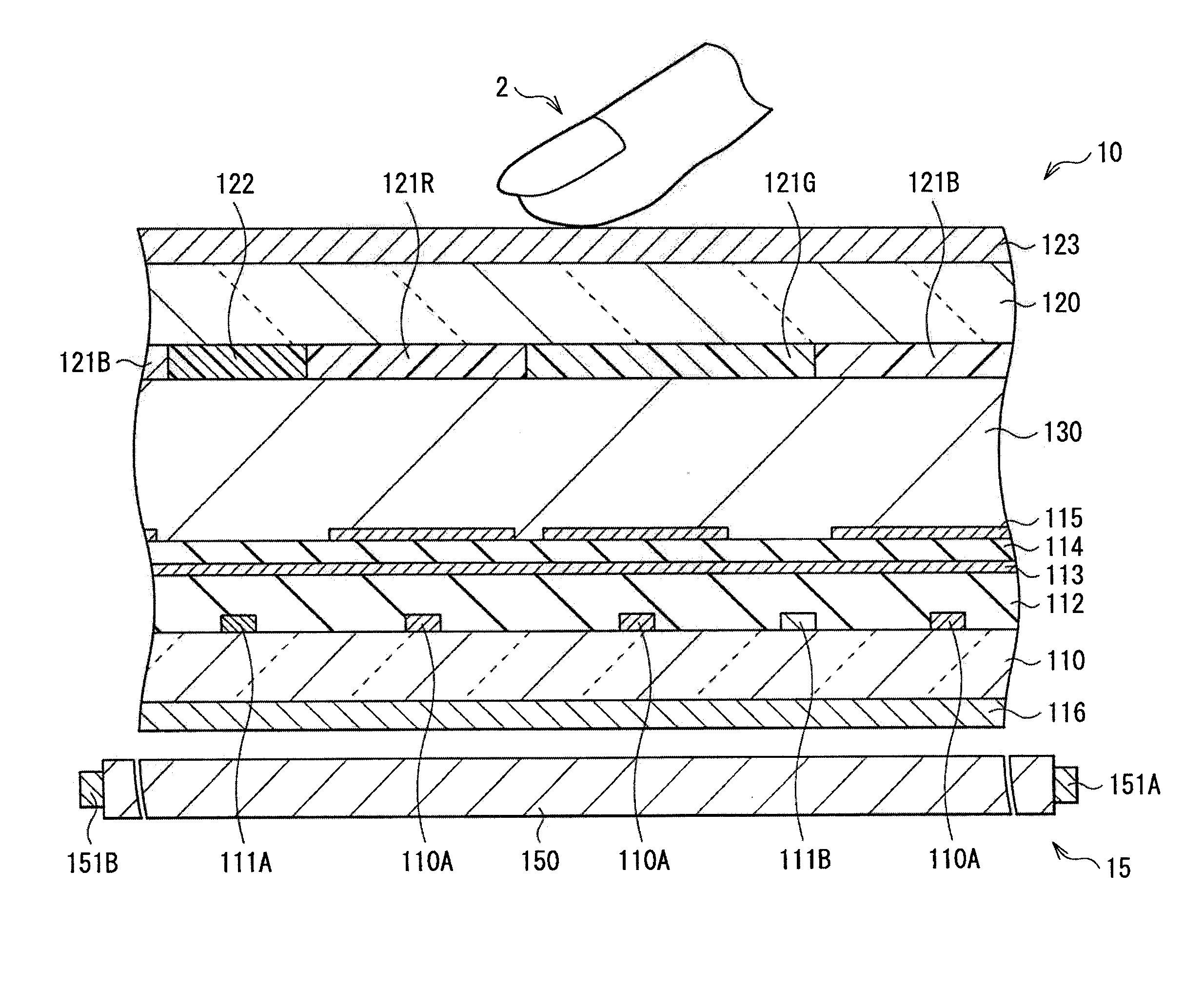
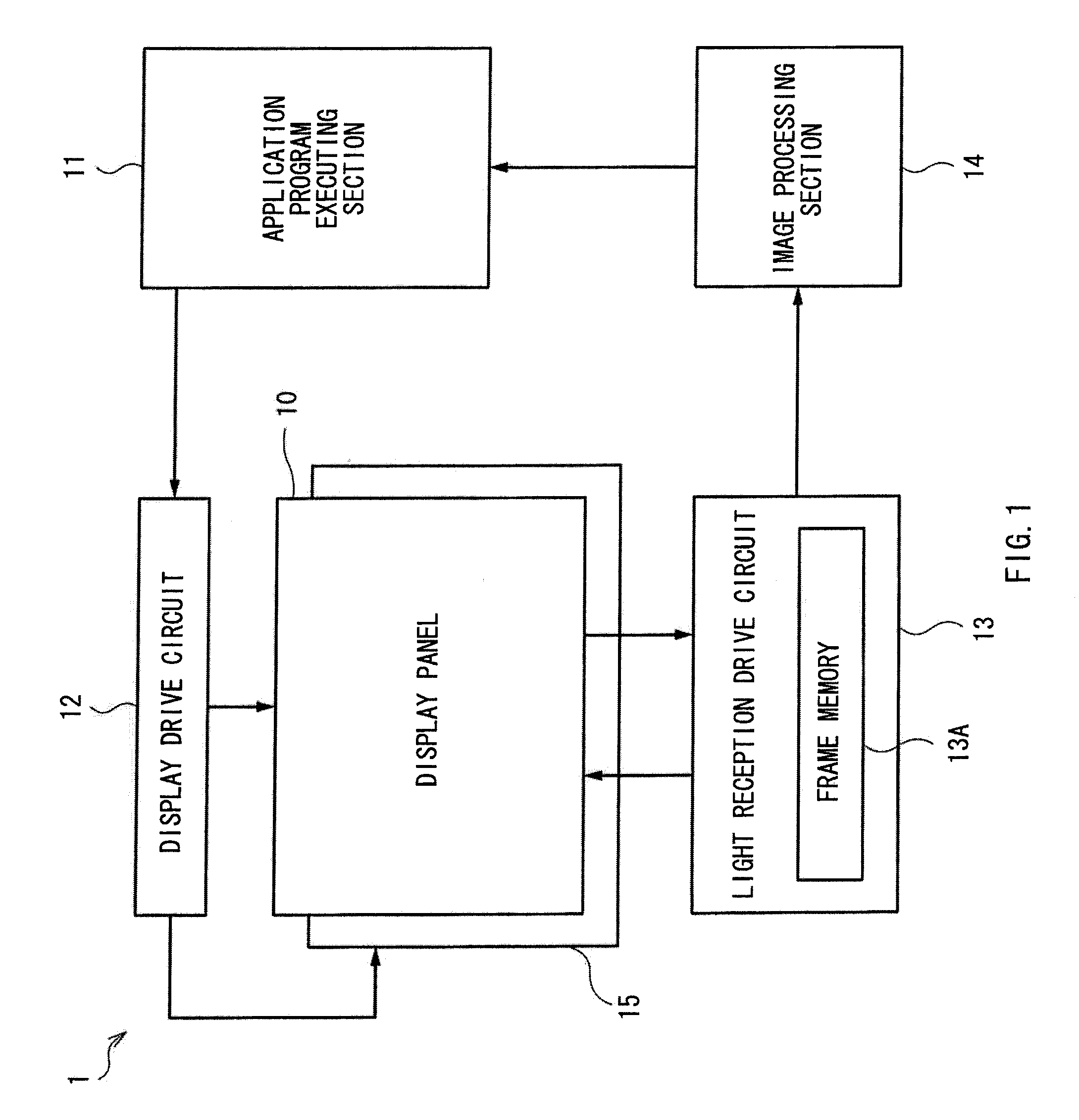
[0043]FIG. 1 illustrates an entire configuration of an image I / O device (image I / O device 1) according to an embodiment of the present invention. The image I / O device 1 is an image display device with an input function that has not only a display function of displaying images such as a predetermined graphic form and a character on a display panel 10 but an input function of obtaining information such as a position or the like of an object which comes in contact with or close to a screen (input function) by capturing an image of the object. The image I / O device 1 includes a display panel 10, a back light 15, a display drive circuit 12, a light reception drive circuit 13, an image processing section 14, and an application program executing section 11.

[0044]The display panel 10 is configured to employ a liquid crystal panel (LCD: Liquid Crystal Display), in which a plurality of pixels are fully arranged in matrix. The back light 15 functions ...

modification 1

(Modification 1)

[0105]FIG. 21 shows a cross-section configuration of a display panel 20 according to Modification 1. The display panel 20 is an organic electroluminescence display in which organic EL devices are used as its display pixels. In the display panel 20, an organic EL device formed on a substrate 110 is enclosed by a substrate 120 with a sealing layer 230 in between. Here, it is to be noted that the back light 15 described in the above-mentioned embodiment is not needed according to the modification.

[0106]A pixel electrode 210 as an anode is formed on a flattening film 112 on the driving substrate 110 for each pixel, and an ultraviolet emission layer 211 is formed thereon as a layer common to each pixel electrode 210 for generating ultraviolet light. A common electrode 212 as a cathode is formed on the ultraviolet emission layer 211. On the common electrode 212, a red conversion layer 213R, a green conversion layer 213G and a blue conversion layer 213B are formed correspon...

application example

(Module and Application Example)

[0113]Subsequently, application example (application examples 1 to 5) of the image I / O device described in the above-mentioned embodiment and modification will be described hereinbelow with reference to FIGS. 22 to 26. The image I / O device of the above-mentioned embodiment etc., may be applied to any kind of electronic unit such as a TV apparatus, a digital camera, a laptop computer, a personal digital assistant device such as a mobile phone, and a video camera. In other words, the image I / O device of the above-mentioned embodiments may be applied to any kind of electronic unit that displays image signals inputted from outside or internally generated as an image or a video. Besides the following examples, application to something like a surveillance camera is also available for example in view of the feature of the present invention that the reflected component is exclusively taken out of detection light.


PUM


Abstract

An image input device capable of acquiring object information irrespective of usage conditions, is provided. The image input device includes a light source, a light source driving section, a first photo-detection element, a photo-detection-element driving section, and an image processing section. The light source driving section drives the light source so that ON period is shorter than OFF period. The photo-detection-element driving section drives the first photo-detection element so that read operations are performed after respective light reception periods which are same in length both in the ON period and in the OFF period. The image processing section generates a first difference image based on an ON image and an OFF image, and acquires the object information based on the first difference image. The ON/OFF images are acquired based on respective output signals from the first photo-detection element in the ON/OFF periods.

Description

[0001]The present application claims priority to Japanese Patent Application No. JP2009-046019 filed in the Japan Patent Office on Feb. 27, 2009, the entire content of which is hereby incorporated by reference.BACKGROUND OF THE INVENTION[0002]1. Field of the Invention[0003]The present invention relates to an image input device, image input-output (hereinafter, referred to as I / O) device and electronic unit allowing position; shape or size of a proximity object such as a finger and a stylus to be optically detected by capturing an image thereof.[0004]2. Description of the Related Art[0005]Recently, electronic units such as a mobile phone, personal digital assistant (PDA), digital still camera, personal computer (PC) monitor and television have a trend of having a function of touch panel using a photosensor. Touch panel is provided with a photosensor and a TFT (thin film transistor) for image display driving, and capable of detecting a position of an object such as a finger and a styl...

Claims


Application Information

Patent Timeline
Patent Type & Authority Applications(United States)
IPC IPC(8): G06F3/042
CPCG06F3/0412G06F3/0421G06F3/0418G06F3/04184G06F3/04182
Inventor FUKUNAGA, YOKOHARADA, TSUTOMUNAKAJIMA, YOSHIHARUTATSUNO, HIROKAZUSENDA, MICHIRU
Owner JAPAN DISPLAY WEST
Why Eureka
Try Eureka