Control device for internal combustion engine

a control device and internal combustion engine technology, applied in the direction of electrical control, process and machine control, instruments, etc., can solve the problem of excessive amount of blowback exhaust gas, and achieve the effect of improving the quality of exhaust emission

Active Publication Date: 2010-09-02
TOYOTA JIDOSHA KK
View PDF9 Cites 7 Cited by
  • Summary
  • Abstract
  • Description
  • Claims
  • Application Information

AI Technical Summary

Benefits of technology

[0011]The invention has been accomplished in view of the foregoing problems, and provides a control device for an internal combustion engine

Problems solved by technology

According to the foregoing control device for an internal combustion engine, if the blowback generation device is operating when the increase

Method used


Image

  • Control device for internal combustion engine
  • Control device for internal combustion engine
  • Control device for internal combustion engine

Examples


first embodiment

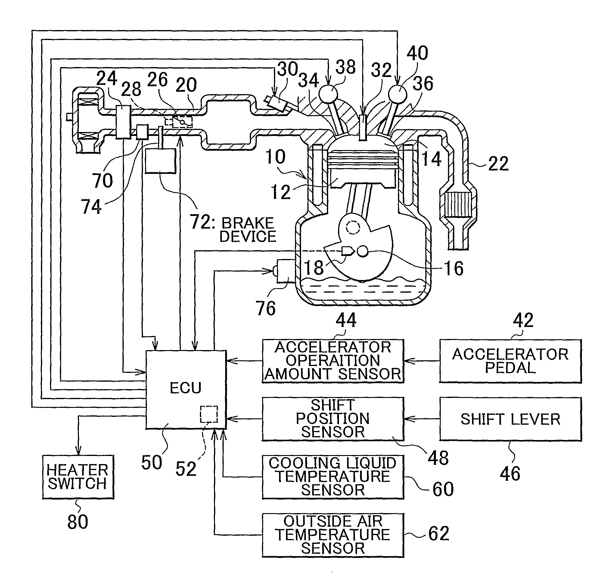
[0110]Firstly, the invention will be described. The usual valve timing control will first be described. The ECU 50 executes the usual valve timing control (hereinafter, referred to as “usual control” when the exhaust valve early-closure control is not executed, for example, when the internal combustion engine is accelerating, or the like. In the usual, control, the ECU 50 controls the opening / closure timing of the valves 34, 36 by operating the VVTs 38, 40 according to the operation state of the internal combustion engine.

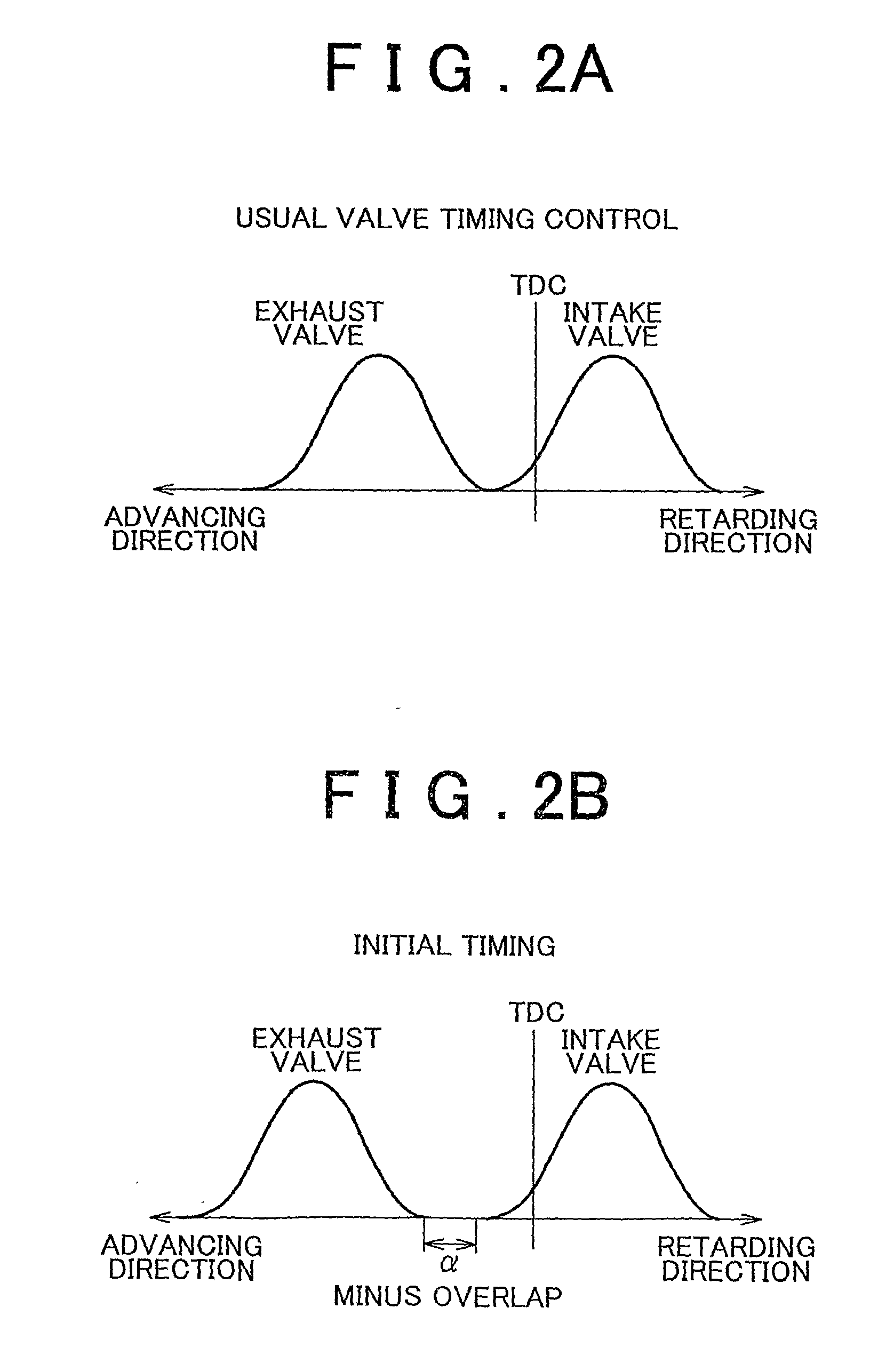
[0111]FIG. 2 shows a relation between the valve lift amount and the crank angle in the usual control. As shown in this diagram, in the usual control, an overlap period during which the open valve durations of the valves 34, 36 overlap with each other is provided near the intake top dead center. Therefore, during the execution of the usual control, the amount of blowback of exhaust gas becomes less than during the execution of the exhaust valve early-closure control...

second embodiment

[0135]Therefore, the second embodiment is constructed so that when the generation of the acceleration request is detected, the exhaust valve early-closure control is prohibited and the usual valve timing control is implemented. Concretely, when the accelerator pedal 42 is depressed by the driver, this depressing operation is detected as an acceleration request by the accelerator operation amount sensor 44. Besides, when the acceleration request is generated, the exhaust valve early-closure control is prohibited, and, in addition, the fuel injection amount is increased so as to avoid the air-fuel ratio becoming lean.

[0136]According to this construction, for example, in the case where the acceleration operation is performed soon after the startup of the engine, or the like, the operation can be promptly detected and the exhaust valve early-closure control can be prohibited. Thus, the control smoothly changes from the exhaust valve early-closure control to the usual valve timing contro...

third embodiment

[0149]Hence, the switching from the exhaust valve early-closure control to the usual valve timing control can be implemented at the time point when the generation of the acceleration request is predicted. That is, the switching of the control can be started in advance before the acceleration request actually starts. Therefore, even during the execution of the exhaust valve early-closure control in which the response delay of the VVT is great, the usual valve timing control can be started at the timing of generation of the acceleration request. Hence, the occurrence of insufficient output or the like during an early period of the acceleration due to response delay of the control can be avoided, and the driveability can be improved.

[0150]FIG. 6 is a flowchart showing a routine that the ECU 50 executes in order to realize a system operation of the third embodiment. Incidentally, the routine shown in FIG. 6 is repeatedly executed from the time of the starting of the internal combustion...


PUM


Abstract

An exhaust valve early-closure control brings about blowback of exhaust gas into an intake system. However, if the exhaust valve early-closure control is executed, for example, during a first idle operation immediately following the startup of the engine, or the like, the amount of blowback exhaust gas becomes excessively large. Therefore, when the post-startup increase amount has decreased to or below a lower-limit criterion value, the ECU prohibits the exhaust valve early-closure control, and changes the control to a usual valve timing control. As a result, during a period during which the combustion state has a stability margin and the amount of emission of HCs and the like is large, the exhaust emission quality can be bettered by the exhaust valve early-closure control. Besides, when the post-startup increase amount has decreased, the combustion state can be stabilized by prohibiting the exhaust valve early-closure control.

Description

BACKGROUND OF THE INVENTION[0001]1. Field of the Invention[0002]The invention relates to a control device for an internal combustion engine and, more particularly, to a control device for an internal combustion engine equipped with a variable valve mechanism that variably sets the valve timing.[0003]2. Description of the Related Art[0004]A control device for an internal combustion engine equipped with a variable valve mechanism is known, as disclosed in, for example, Japanese Patent Application Publication No. 2001-355462 (JP-A-2001-355462). This kind of control device for internal combustion engines according to the related art has a construction in which an exhaust valve early-closure control is executed when an internal combustion engine is undergoing a low-speed and low-load operation.[0005]In the exhaust valve early-closure control, the exhaust valve closure timing is advanced by operating a variable valve mechanism. As a result, in the vicinity of the intake top dead center, a...

Claims


Application Information

Patent Timeline
IPC IPC(8): F02D41/00F01L1/34F01N1/00
CPCF02D13/0265Y10T477/68F02D41/0225F02D41/045F02D41/047F02D41/068F02D41/08F02D41/34F02D2041/001F02D2200/0406F02D2200/0414F02D2200/502F02D2250/41Y02T10/47Y02T10/18F02D41/006Y02T10/12Y02T10/40
Inventor ISHII, DAISUKEYOSHIOKA, MAMORUTOMIMATSU, MAKOTO
Owner TOYOTA JIDOSHA KK
Why Eureka
Try Eureka