Modeling In Sedimentary Basins

a sedimentary basin and model technology, applied in the field of computer modeling, can solve the problems of high overpressure, inability to accept the approach, complex numerical modeling of such a coupled process, etc., and achieve the effect of simplifying the compaction phenomenon

Inactive Publication Date: 2010-09-02
MALIASSOV SERGUEI
View PDF24 Cites 36 Cited by
  • Summary
  • Abstract
  • Description
  • Claims
  • Application Information

AI Technical Summary

Benefits of technology

[0009]While modeling compaction processes and fluid flow, a sediment system is considered that comprises a porous solid phase whose interstitial volume is saturated with a liquid which is called the pore fluid. Due to the action of gravity and the density difference between the solid and liquid phases, the solid phase compacts under its own weight (and the weight of other layers) by reducing its porosity, thus leading to the expulsion of the pore fluid out of the solid phase matrix.
[0010]Embodiments of the invention use a continuum mechanics approach to express equations for the conservation of mass and momentum. Embodiments of the invention assume a one-dimensional vertical compaction to simplify the compaction phenomena. This allows embodiments of the invention to simultaneously solve equations for both fluid flow and compaction.
[0013]Embodiments of the invention operate to produce basin models in a much more efficient manner, in less time, and using less computational resources. Embodiments of the invention allow for compaction and fluid flow to be solved simultaneously rather than using repeated iterations. Embodiments of the invention produce accurate results even when the geologic basin is undergoing rapid change, e.g. high rates of deposition of sediment.

Problems solved by technology

Numerical modeling of such a coupled process is complex and has been historically carried out in three areas: geo-mechanical modeling with the primary goal of computing stress-strain behavior, fluid flow modeling in porous media, and fracture mechanics.
Thus, such an approach is unacceptable in situations where there is strong coupling between these processes, for example, in situation of high deposition rate, when rapid changes of porosity and permeability due to stress changes lead to under-compaction, formation of high overpressure with respect to the hydrostatic distribution and, possibly, fracturing of the solid media.

Method used


Image

  • Modeling In Sedimentary Basins
  • Modeling In Sedimentary Basins
  • Modeling In Sedimentary Basins

Examples


Embodiment Construction

[0031]Embodiments of the invention are useful for modeling subsurface oil fields. The examples of the embodiments described herein may reference such oil fields. However, the embodiments may be used to model other domains involving other materials and / or processes. For example, embodiments can be used to model distribution of contaminant liquids in the subsurface basin, migration of radioactive substances from the underground storage facilities, or migration of other liquids, water, natural gas, or other gases.

[0032]The data used in such simulations can be derived by various techniques such as stratigraphic analysis, seismic inversion, or geological interpretation of those by geoscientists, using sensors to measure various characteristics of the basin.

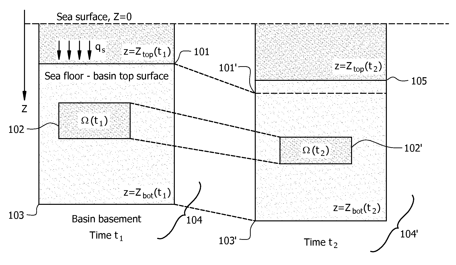
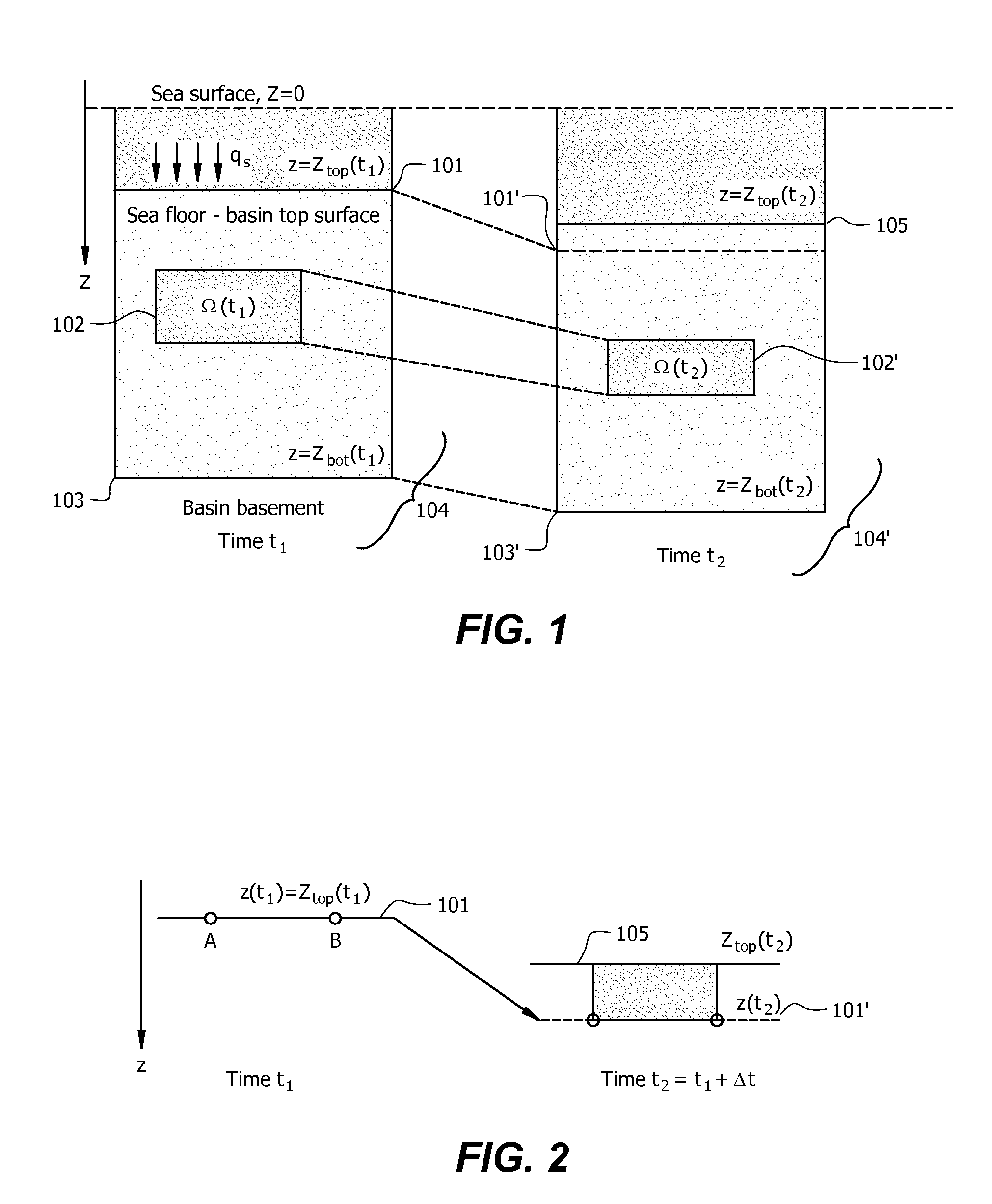
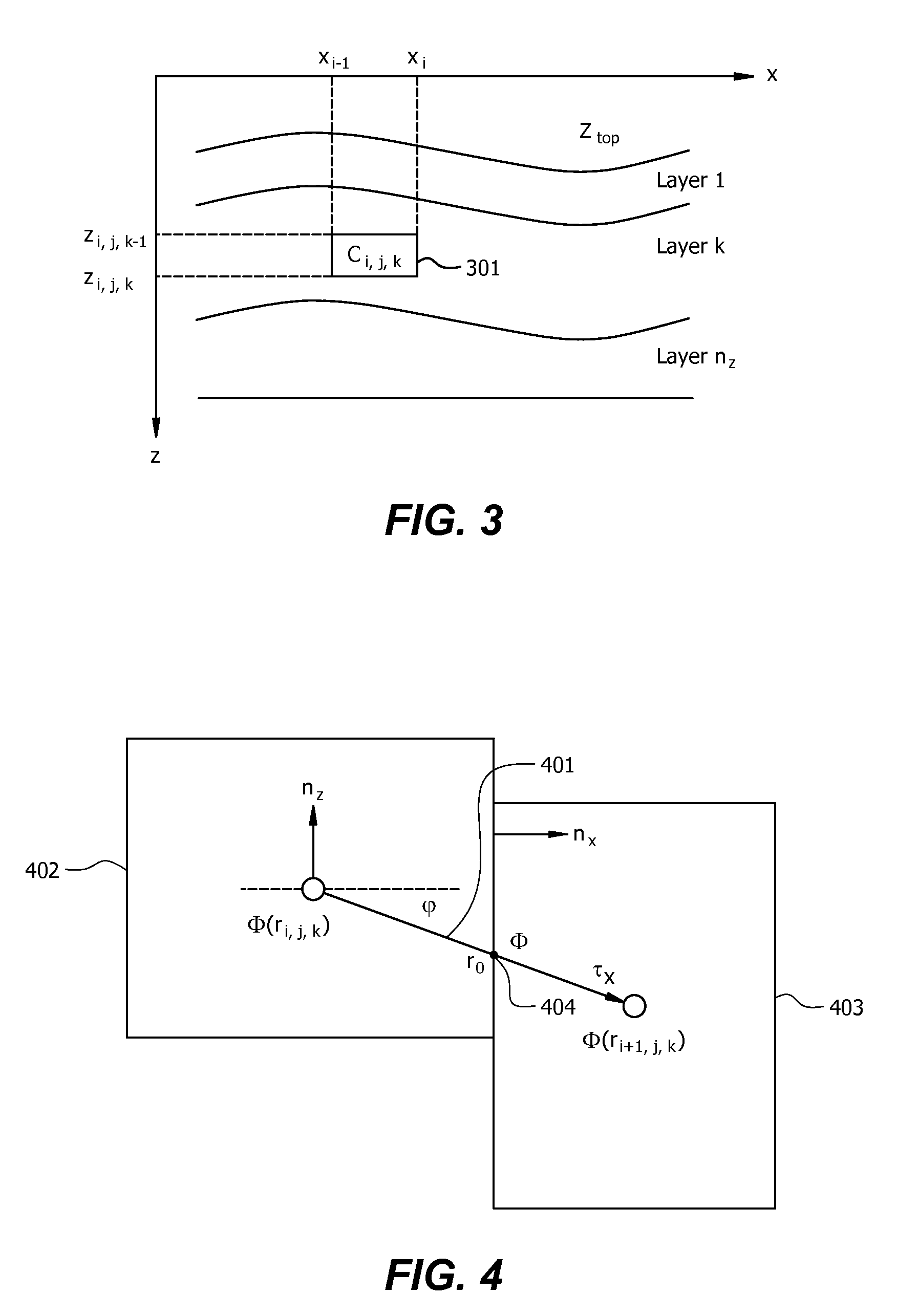
[0033]The following describes compaction, decompaction, and fluid flow modeling according to embodiments of the invention. The models preferably take into account a version of mechanical equilibrium of the media. In the description, a ...


PUM


Abstract

Embodiments of the invention operate to produce basin models that describe the basin in terms of compaction and fluid flow. The equations used to define compaction and fluid flow may be solved simultaneously. Embodiments of the invention use equations that define a set of unknowns that are consistent over the basis. The equations may define total pressure, hydrostatic pressure, thicknesses, and effective stress.

Description

CROSS-REFERENCE TO RELATED APPLICATION[0001]This application claims the benefit of U.S. Provisional Patent Application 61 / 008,801 filed Dec. 21, 2007 entitled MODELING IN SEDIMENTARY BASINS, attorney docket number 2007EM385, the entirety of which is incorporated by reference herein.TECHNICAL FIELD[0002]This application relates in general to computer modeling, and more specifically to modeling pressure in sedimentary basins.BACKGROUND OF THE INVENTION[0003]In geological exploration, it is desirable to obtain information regarding the various formations and structures that exist beneath the Earth's surface. Such information may include geological strata, density, porosity, composition, etc. This information is then used to model the subsurface basin to predict the location of hydrocarbon reserves and aid in the extraction of hydrocarbon.[0004]Basin analysis is the integrated study of sedimentary basins as geodynamical entities. Sedimentary basins are studied because the basins contain...

Claims


Application Information

Patent Timeline
Patent Type & Authority Applications(United States)
IPC IPC(8): G06G7/50G06F17/11
CPCG01V99/00
Inventor MALIASSOV, SERGUEI
Owner MALIASSOV SERGUEI
Why Eureka
Try Eureka