Systems and Methods for Electrified Fish Barriers

a technology of electrification and fish, applied in pisciculture and aquaria, hydraulic engineering apparatus, construction, etc., can solve the problems of increasing the degradation of the electrode, increasing the operational cost, and all the electrodes experiencing degradation, so as to achieve a smaller width, increase the electrical field, and increase the effect of energy

Inactive Publication Date: 2010-09-09
SMITH ROOT
View PDF10 Cites 12 Cited by
  • Summary
  • Abstract
  • Description
  • Claims
  • Application Information

AI Technical Summary

Benefits of technology

[0014]The present inventive subject matter overcomes problems in the prior art by providing an electrical barrier for the deterrence of fish havin a soft start pulsator unit; the soft start pulsator unit having a anode and a cathode, the anode and cathode capable of generating an energy increasing electrical field; an electrode array, the electrode array electrically connected to the soft start pulsator unit; wherein the electrode array has a plurality of anode leads and a plurality of cathode leads, the anode leads electrically connected to the anode leads and the cathode leads connected to the cathode; a support structure, the support structure mechanically connected to the electrode array, such that the anode leads and the cathode leads are separated and generate the energy increasing electrical field when the anode leads and the cathode leads are immersed in water; such that when the energy increasing electrical field is generated between the anode leads and the cathode leads so that fish will be deterred by the electrical barrier. The electrical barrier for the deterrence of fish further has an energy increasing field further having a constant current source; a time varying voltage source, the time varying voltage source increasing from a minimum potential to a maximum potential; such that the product of the constant current source and the time varying voltage source will transfer increasing amounts of energy to the fish thereby evoking a flight response. The electrical barrier for the deterrence of fish further has a time varying voltage source with a sine-like waveform. The electrical barrier for the deterrence of fish having a time varying voltage source further has a triangle-like waveform. The electrical barrier for the deterrence of fish according to claim 1 wherein the energy increasing field has a constant voltage source, a time varying current source, the time varying current source increasing from a minimum potential to a maximum potential; such that the product of the constant voltage source and the time varying current source will transfer increasing amounts of energy to the fish thereby evoking a flight response. The electrical barrier for the deterrence of fish having an energy increasing field having a time varying voltage source, the time varying voltage source increasing from a minimum potential to a maximum potential; a time varying current source, the time varying current source increasing from a minimum potential to a maximum potential; such that the product of the time varying voltage source and the time varying current source will transfer increasing amounts of energy to the fish thereby evoking a flight response. The electrical barrier for the deterrence of fish having an energy increasing field having a time varying pulse-width modulated voltage source, the time varying pulse-width modulated voltage source increasing from a minimum potential to a maximum potential and having pulse widths that increase from a smaller width to a longer width; a time varying current source, the time varying current source increasing from a minimum potential to a maximum potential; such that the product of the time varying voltage source and the time varying current source will transfer increasing amounts of energy to the fish thereby evoking a flight response.

Problems solved by technology

Unfortunately, the continuous operation of the electrical barrier results in higher operational costs due to energy costs and increased maintenance.
This may be inefficient during periods of time where there is no passage of fish.
Furthermore, all electrodes experience degradation as a consequence of the electrolytic action of the electrode with the water.
Therefore a continuously operating barrier will cause maximum amount of electrolytic action of the electrodes and consequently, increased degradation of the electrodes.
One of the problems of electrical fish barrier “turn-on” and / or pulsator initiation, is the undesired side effect that may occur for certain bottom dwelling species of fish (e.g., sturgeon) that may be located near the electrode array or perhaps nestled against an electrode.
The application of an operational voltage by the pulsator to electrode array may result in immediate electrotaxis and / or physiological damage to the fish due to an electrically induced convulsive response.
Some of these fish are commercially valuable and thus any damage due to the effects of the electrical barrier being energized may diminish their potential catch value.

Method used


Image

  • Systems and Methods for Electrified Fish Barriers
  • Systems and Methods for Electrified Fish Barriers
  • Systems and Methods for Electrified Fish Barriers

Examples


Embodiment Construction

[0065]Representative embodiments according to the inventive subject matter are shown in FIGS. 1-11, wherein similar features share common reference numerals.

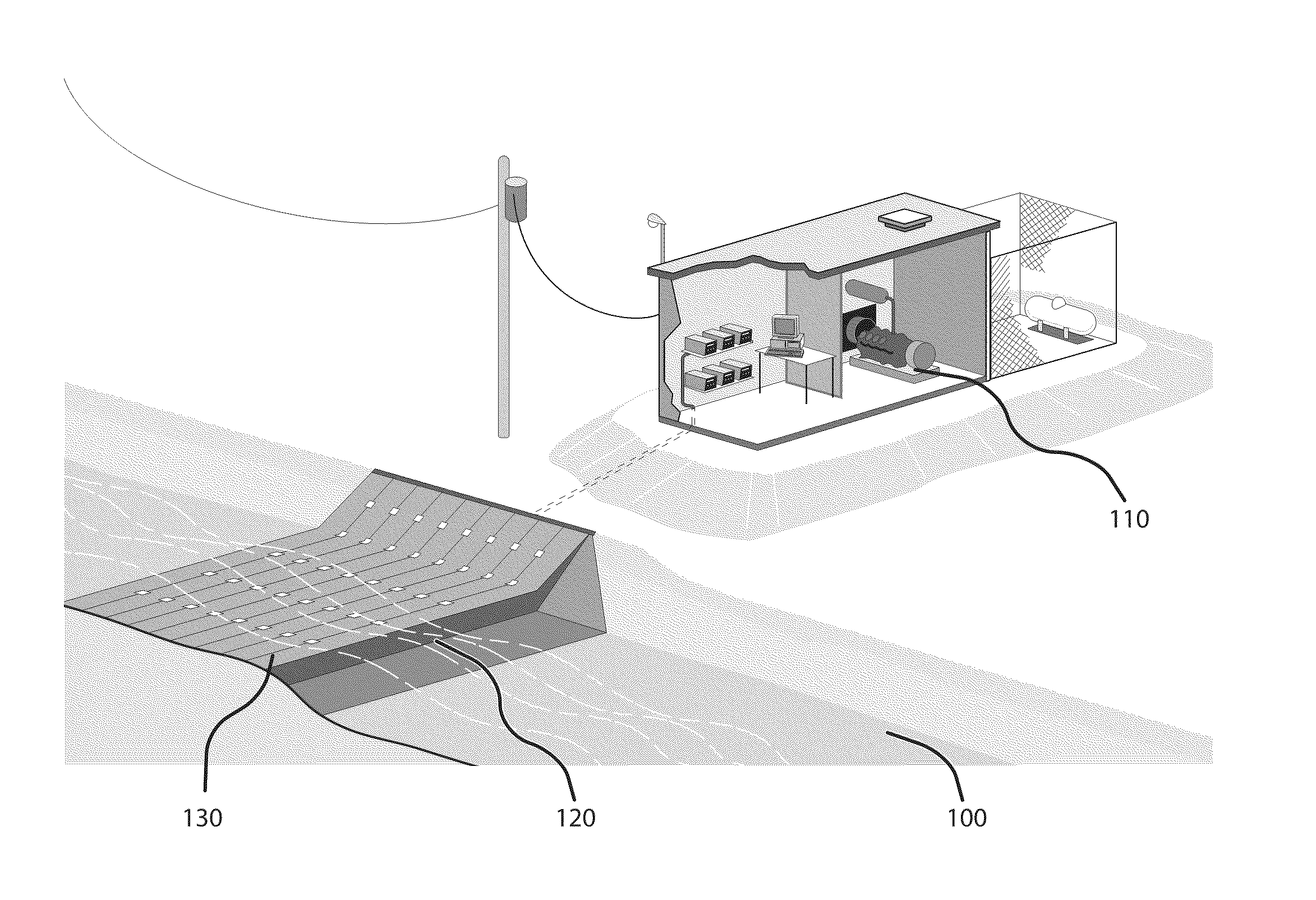
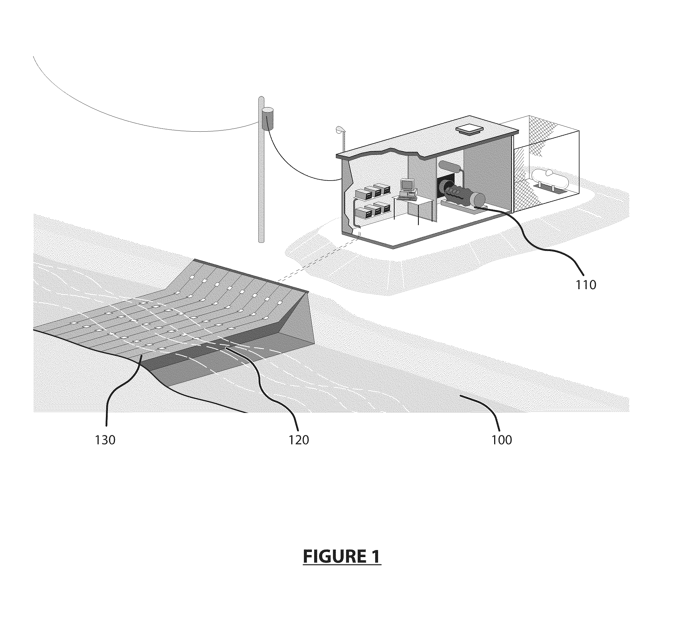
[0066]Now referring to prior art FIG. 1 which illustrates the typical electrical barrier system. This system configuration is an electrified fish barrier 100 which has a pulsator unit 110, an electrode array support structure 120, and an electrode array 130. The pulsator unit 110 provides electrical output as either AC (alternating current) or DC (Direct Current) waveforms. These electrical waveforms may be either continuous or intermittent (e.g. pulsed). The electrical current is passed to the electrode array 130 which is affixed to the support structure 120. During operation, the fish (not shown) that are proximate to the electrode array 130 while the pulsator unit 110 is operating will be entrained or repulsed from the barrier.

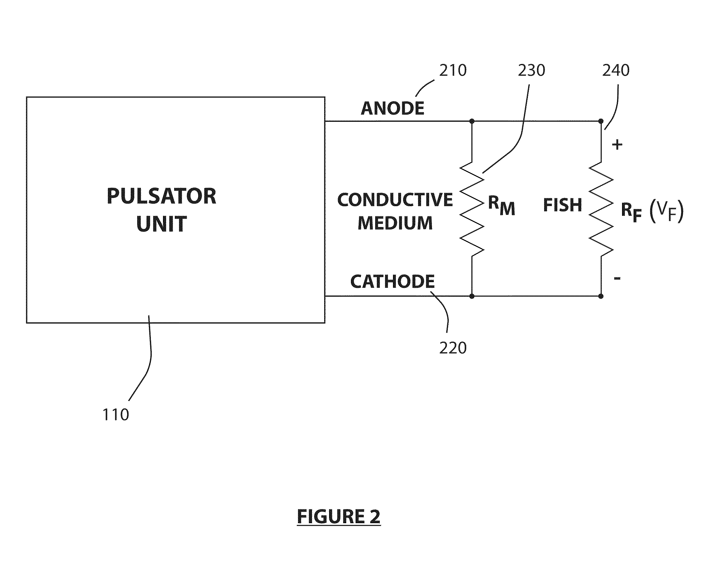
[0067]Now referring to prior art FIG. 2 that illustrates a schematic diagram of the pulsator unit 11...


PUM


Abstract

The inventive subject matter describes an electrical barrier for the deterrence of fish having an, the electrical barrier with a computer system capable of executing a modified soft-start algorithm, the computer system further having a detector input and a switch output; a bio-electric fish proximity detector, the bio-electric fish proximity detector having a anode-cathode detecting pair input and a signal output, wherein said signal output is connected to the detector input; a time varying voltage source.

Description

RELATED APPLICATIONS[0001]This application claims the benefit of U.S. Provisional Application No. 61 / 157,803, filed Mar. 5, 2009, the contents herein incorporated into this application by referenceBACKGROUND[0002]The present inventive subject matter relates to the use of electric fields to guide fish and other aquatic animals and to prevent injury thereof.[0003]The effect of electric currents on fish are well known in the prior art of electrofishing. Electrofishing involves the use of electric currents to attract and / or repel fish with the intent of creating aquatic barriers and / or to improve sample yields during fish conservation activities.[0004]Electrofishing has traditionally been used in freshwater lakes and streams and is the subject of U.S. Pat. Nos. 5,327,854; 4,750,451; 4,672,967; 4,713,315; 5,111,379; 5,233,782; 5,270,912; 5,305,711; 5,311,694; 5,327,668; 5,341,764; 5,551,377; and 6,978,734 which are incorporated herein by reference. Also, electrofishing has been the used ...

Claims


Application Information

Patent Timeline
Patent Type & Authority Applications(United States)
IPC IPC(8): A01K61/00
CPCE02B1/006A01K79/02A01K61/00Y02A40/81
Inventor BURGER, CARLSMITH, JEFFERY
Owner SMITH ROOT
Why Eureka
Try Eureka