Apparatus and Method for Temperature Mapping a Rotating Turbine Component in a High Temperature Combustion Environment

a technology of combustion environment and thermal imaging apparatus, which is applied in the field of thermal imaging apparatus and techniques for temperature mapping a rotating turbine component in a high temperature combustion environment, can solve the problems of inability to meet the requirements of high-temperature combustion environmen

Inactive Publication Date: 2010-09-09
SIEMENS ENERGY INC
View PDF7 Cites 35 Cited by
  • Summary
  • Abstract
  • Description
  • Claims
  • Application Information

AI Technical Summary

Problems solved by technology

Long-term exposure of these ceramic coatings to the hostile, high temperature, abrasive environment in which such turbines typically operate can cause phase destabilization, sintering, microcracking, delamination and ultimately spallation within the coating layers, exposing the superalloy component and possibly resulting in rapid degradation or failure and potentially requiring costly and burdensome repairs.
However, such an approach would not be a feasible approach in a high temperature combustion environment of a turbine, where operating temperatures change as a function of the load of the turbine.
Moreover, the system described by U.S. Pat. No. 7,422,365 appears to be limited to thermally imaging non-moving objects.
Accordingly, such a system would not be suitable for temperature mapping a rotating turbine component.
However, temperature measurement errors can be introduced due to various factors, which under prior techniques have not been appropriately accounted for.

Method used


Image

  • Apparatus and Method for Temperature Mapping a Rotating Turbine Component in a High Temperature Combustion Environment
  • Apparatus and Method for Temperature Mapping a Rotating Turbine Component in a High Temperature Combustion Environment
  • Apparatus and Method for Temperature Mapping a Rotating Turbine Component in a High Temperature Combustion Environment

Examples


Embodiment Construction

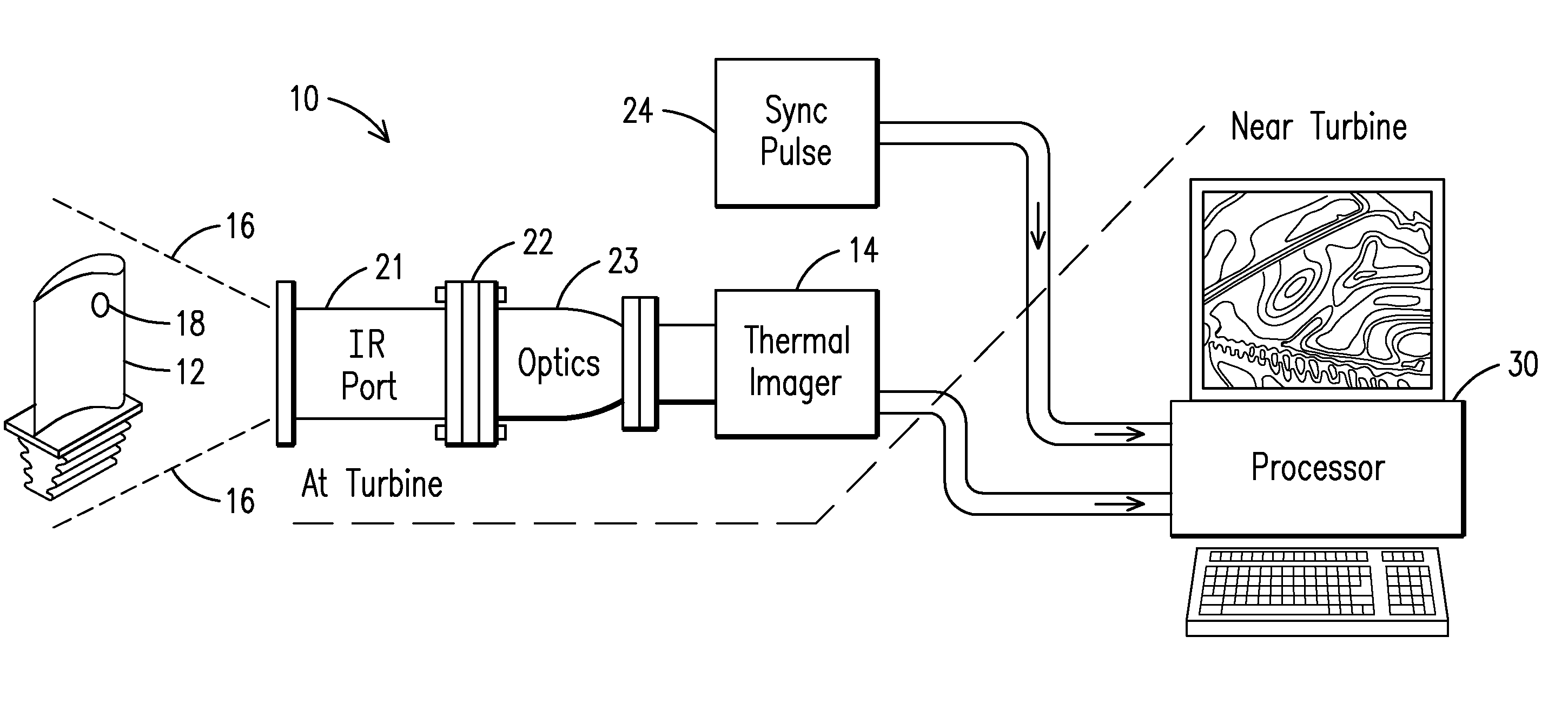
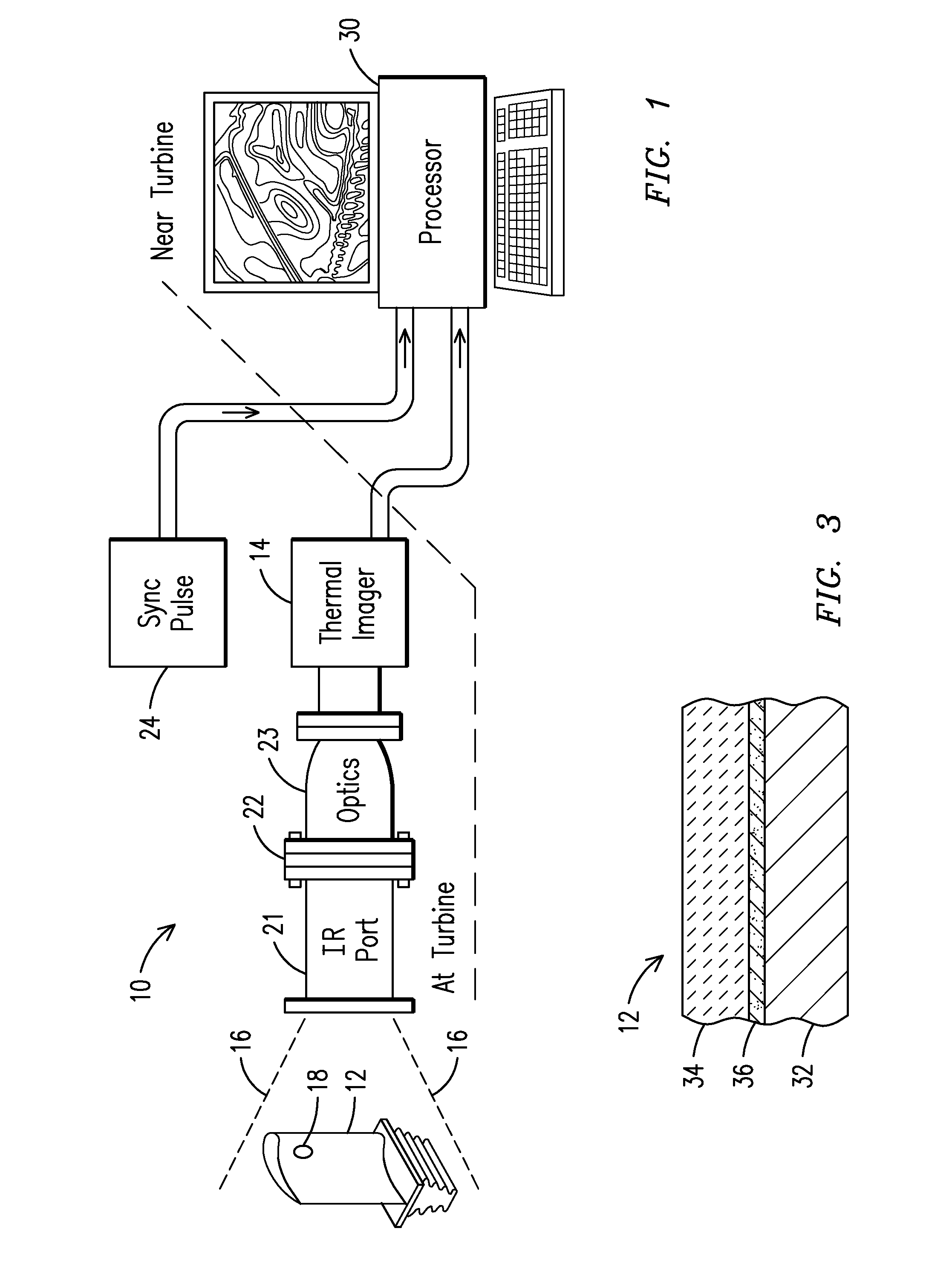
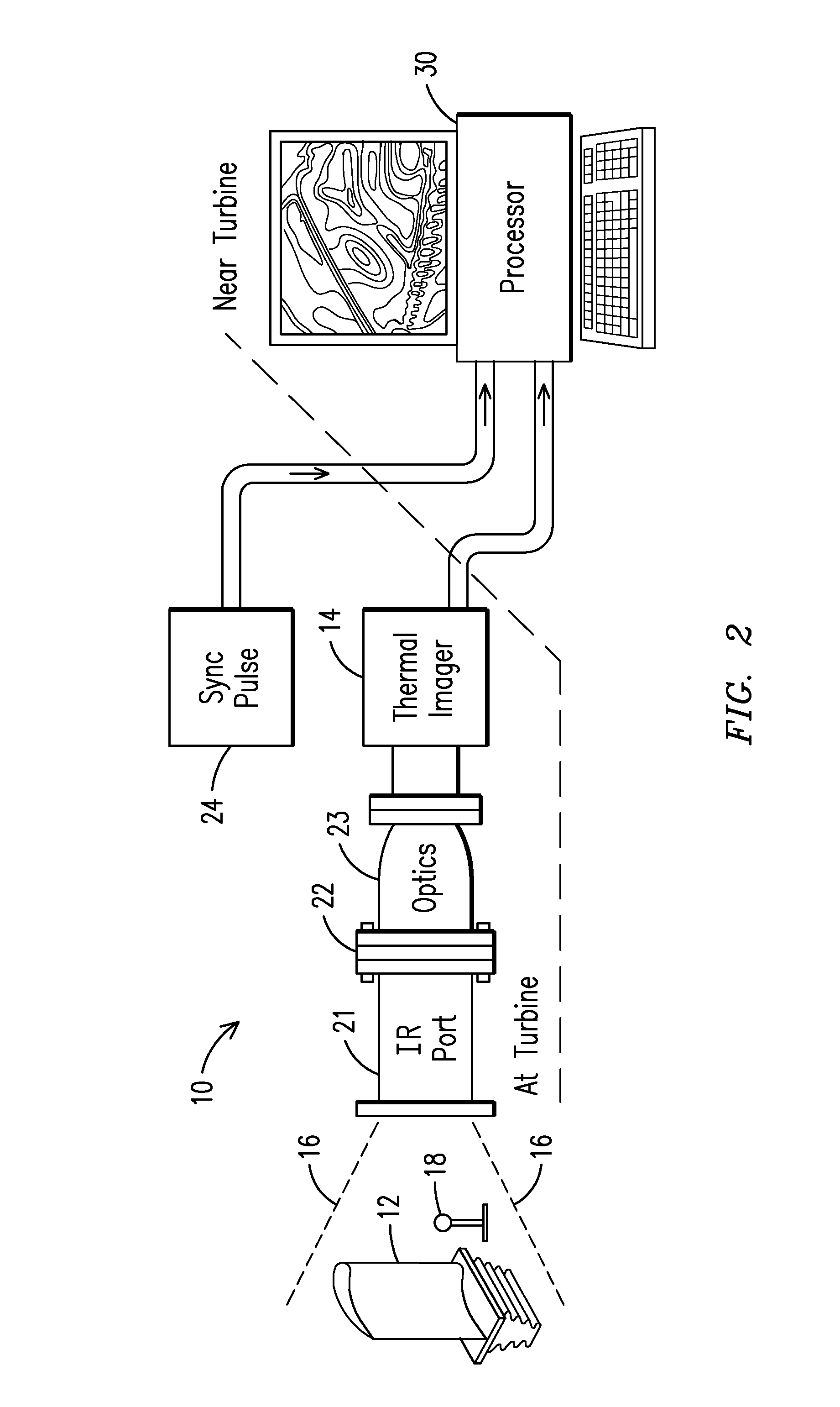
[0013]In accordance with one or more embodiments of the present invention, structural arrangements and / or techniques conducive to accurate measurements of the absolute temperature of a rotating component, such as a turbine blade, essentially in real-time are described herein. In the following detailed description, various specific details are set forth in order to provide a thorough understanding of such embodiments. However, those skilled in the art will understand that embodiments of the present invention may be practiced without these specific details, that the present invention is not limited to the depicted embodiments, and that the present invention may be practiced in a variety of alternative embodiments. In other instances, methods, procedures, and components, which would be well-understood by one skilled in the art have not been described in detail to avoid unnecessary and burdensome explanation.

[0014]Furthermore, various operations may be described as multiple discrete ste...


PUM

PropertyMeasurementUnit
speedsaaaaaaaaaa
speedsaaaaaaaaaa
emissivity coefficientaaaaaaaaaa

Abstract

Apparatus and method for temperature mapping a rotating component (12) in a high temperature combustion environment. The apparatus includes a thermal imager (14) having a field of view to sense infrared (IR) emissions. Emissivity of a surface of the component is subject to variation in the combustion environment. A radiance emitter (18) defines a spot within the field of view of the thermal imager. The spot indicates a respective emissivity value. A processor (30) is connected to the thermal imager to generate a radiance map of the component based on the IR emissions from the component. The processor includes a thermal calibration module configured to calibrate the radiance map based on the emissivity value of the spot within the field of view of the thermal imager to generate a calibrated thermal map of the component that displays absolute temperature over the surface of the component.

Description

CROSS-REFERENCE TO RELATED APPLICATION[0001]This application claims benefit of the 6 Mar. 2009 filing date of U.S. provisional patent application No. 61 / 158,088, which is incorporated by reference in its entirety herein.FIELD OF THE INVENTION[0002]The present invention is generally related to thermography, and, more particularly, to a thermal imaging apparatus and techniques for temperature mapping a rotating turbine component in a high temperature combustion environment.BACKGROUND OF THE INVENTION[0003]It is known to use various superalloy materials, such as cobalt or nickel-based superalloys, for making blades, vanes and other components for power generating turbines, propulsion equipment, etc. These turbines can operate at relatively high temperatures and are generally protected by a series of protective coatings. The coatings may comprise layers of metallic base coats, thermally grown oxide layers, as such layers grow in service-run components and a final ceramic thermal barrier...

Claims


Application Information

Patent Timeline
Patent Type & Authority Applications(United States)
IPC IPC(8): G02F1/01G01D18/00
CPCG01D18/008G01J5/0022G01J5/0088G01J5/02G01J5/025G02B13/16G01J5/042G01J5/08G01J5/0803G01J5/0846G01J5/04
Inventor LEMIEUX, DENNIS H.ZOMBO, PAUL J.JONNALAGADDA, VINAY
Owner SIEMENS ENERGY INC
Why Eureka
Try Eureka