Power generator and power generation system including this power generator

a power generator and power generation technology, applied in the direction of electric generator control, magnetic circuit shape/form/construction, magnetic circuit rotating parts, etc., can solve the problem of low effective power generation rate, inability to obtain stable electric power, and change in energy such as wind power or water power, so as to prevent abnormally high frequency of power to be generated, stable power generation, and increase the effect of inductan

Active Publication Date: 2010-09-09
NISCA KK
View PDF3 Cites 26 Cited by
  • Summary
  • Abstract
  • Description
  • Claims
  • Application Information

AI Technical Summary

Benefits of technology

[0012]According to the present invention, as described above, the effective output winding wires whose number is three or its multiple number and which constitute the plurality of coreless winding wires are connected to the three-phase output terminal through the switching means so as to enable switching the total number of turns to a large or small value, and this switching means is changed over in accordance with an intensity of the rotating force from the driving source, thereby demonstrating the following effect.
[0013]When the total number of turns of the winding wires that produce electromotive force is set large even though external energy, e.g., wind power is excessively small (slight wind), an inductance can be increased. Therefore, a current produced in the coil increases to be output to the outside. Additionally, when the external energy excessively increases to become high wind or the like and the driving rotary shaft rotates at an extremely high speed, a frequency of the power to be generated can be prevented from abnormally rising by changing an inductance value of the power generating coil to a small value, thus enabling stable power generation.

Problems solved by technology

Therefore, effective power generation cannot be performed at a low wind velocity.
When the magnet rotor is driven and rotated to produce electromotive force in a stator coil as described above, a change in energy such as wind power or water power becomes a problem.
That is, it is known that in the synchronous generator, the cogging torque acts on a driving rotary shaft that rotates at a lower speed when rotating force of wind power or the like is small, so that stable electric power cannot be obtained.
Further, likewise, when the rotating force of the wind power or the like is excessive, the rotary shaft rotates at an excessively high speed, and a frequency of electric power generated in the coil increases.
When the electric power to be output is connected with an electric power system, reducing a rotating speed of an input source to be lower than a synchronous speed results in a decrease in frequency, and increasing the rotating speed to be higher than the synchronous speed results in a rise in frequency, thereby leading to a problem that the stable electric power cannot be obtained.
Since this type of power generation system is installed in a place where an input in a predetermined range (predetermined strength) can be obtained, using the system for extensive purposes, especially installing the system as a small facility is difficult.

Method used


Image

  • Power generator and power generation system including this power generator
  • Power generator and power generation system including this power generator
  • Power generator and power generation system including this power generator

Examples


first embodiment

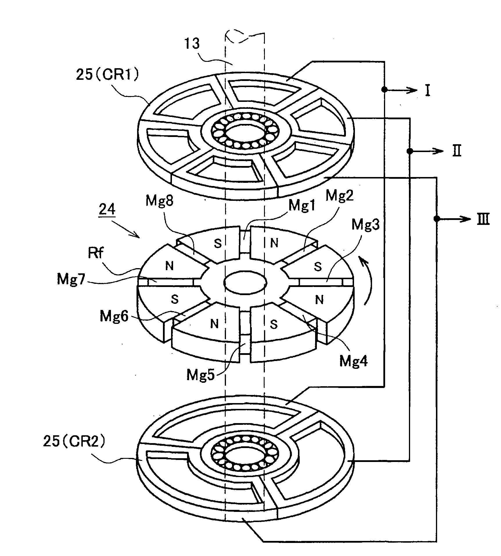
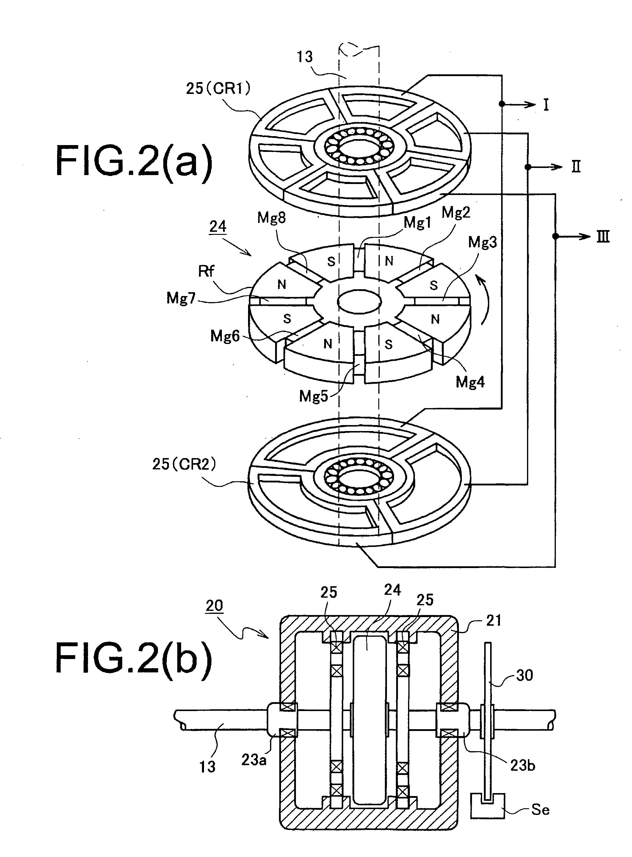
[0036]As shown in FIGS. 5(a) and (b), a magnet rotor 24 includes magnetic poles Mn1 to Mn8 having eight (a multiple number of 4) N and S poles annularly alternately arranged and a rotary shaft 13. A line x-x in the drawing denotes the center of rotation. Moreover, in a stator coil 25, a first coil body CR1 and a second coil body CR2 having the same configuration are arranged on a front surface side and a back surface side of the magnet rotor 24, respectively. Each of the first and second coil bodies CR includes six winding wires Co1 to Co6 as depicted in FIG. 5(b), and a pair of Co1 and Co4, a pair of Co2 and Co5, and a pair of Co3 and Co6 are electrically wire-connected, electromotive force having the same phase being produced in each pair. The first and second coil bodies CR1 and CR2 are wire-connected through switching means 35 as depicted in FIG. 5(a). Additionally, a large inductance is set when this switching means 35 is wire-connected in a direction indicated by Sa in the dra...

second embodiment

[0037]As shown in FIG. 6(a) and FIG. 6(b), a magnet rotor 24 includes magnetic poles Mn1 to Mn8 having eight (a multiple number of 4) N and S poles annularly alternately arranged and a rotary shaft 13 (the same configuration as the first embodiment). Further, in a stator coil 25, a first coil body CR1 and a second coil body CR2 are arranged on a front surface side and a back surface side of the magnet rotor 24, respectively. This first coil body CR1 includes Co1, Co2, Co3, Co4, Co5, and Co6, and a pair of Co1 and Co4, a pair of Co2 and Co5, and a pair of Co3 and Co6 are electrically wire-connected, electromotive force having the same phase being produced in each pair.

[0038]On the other hand, the second coil body CR2 includes three winding wires Co1 to Co3. Such first and second coil bodies CR1 and CR2 are wire-connected through switching means 36 as depicted in FIG. 6(a). Furthermore, when this switching means 36 is wire-connected in a direction indicated by Sa in the drawing, elect...


PUM


Abstract

According to the present invention, there is provided a power generator that can generate power having a predetermined voltage and a predetermined current even though external energy is slight or excessively strong when generating power based on water power or wind power, the power generator comprising: a magnet rotor that rotates upon receiving rotating force from a driving source; and a stator coil arranged to face magnetic poles of the magnet rotor, the magnet rotor including: a rotary shaft rotatably and axially supported by a housing; and permanent magnets that form a plurality of magnetic poles on a concentric circle with the rotary shaft at the center. The stator coil includes: a plurality of coreless winding wires arranged to face the magnetic poles formed in the rotor; and a three-phase output terminal. Thus, the plurality of coreless winding wires are formed of effective output winding wires whose number is three or its multiple number, and they are connected with the output terminal through switching means so as to enable switching a total number of turns to a large or small value. This switching means is connected to controlling means in such a manner that the total number of turns is reduced when the rotating force from the driving source is large and the total number of turns is increased when the rotating force is small.

Description

BACKGROUND OF THE INVENTION[0001]The present invention relates to a power generator that converts fluid energy such as wind power, water power, or heat into electrical energy and a power generation system including this power generator, and relates to an improvement in a power generation mechanism.[0002]In general, this type of power generation apparatus is widely known as an apparatus that converts energy such as wind power, water power, or heat into electrical energy. Further, a mechanism that uses external energy to rotate a spinning rotor having the same power generation principle as that of a power generator and outputs an electric current produced in a coil by the rotating force is also widely known.[0003]As a conventionally known power generator, for example, Patent Document 1 (Japanese Patent Application Laid-open No. 2008-086128) discloses a configuration that a magnet rotor having a plurality of magnetic poles arranged in a rotating direction is rotatably disposed to a hou...

Claims


Application Information

Patent Timeline
Patent Type & Authority Applications(United States)
IPC IPC(8): H02P9/04H02P9/48H02K21/24F03B13/00
CPCF03D9/003F05B2210/16H02K3/28Y02E10/72H02K7/083H02K21/24H02K7/1823H02K3/47F03D9/255F03D80/88F03D15/10
Inventor HAYAKAWA, YUKIHIKO
Owner NISCA KK
Why Eureka
Try Eureka