Cold-cathode lamp, and display illumination device and display device therewith

Active Publication Date: 2010-09-09
SHARP KK
14 Cites 2 Cited by

AI-Extracted Technical Summary

Problems solved by technology

Inconveniently, however, not only does this configuration require as many power supply circuits as there are cold-cathode lamps, incurring accordingly high costs, but it also thwarts size reduction, weight reduction, and cost reduction.
This makes the fitting of cold-cathode lamps troublesome, resulting in low efficiency of the assembly of illumination devices and the like employing cold-cathode lamps, and also makes the removal of cold-cathode lamps troublesome, resulting in low efficiency of the replacement of cold-cathode lamps, and of the disassembly of illumination devices and the like employing cold-cathode lamps.
Inconveniently, however, in an external-electrode fluorescent lamp, since the glass between the external electrodes and ...

Benefits of technology

[0025]To overcome the inconveniences and problems discussed above, preferred embodiments of the present invention provide a cold-cathode lamp that can be lit in parallel by being driven in para...

Abstract

A cold cathode lamp includes a light-transmitting insulating tube, first and second internal electrodes arranged inside the insulating tube, first and second external electrodes arranged outside the insulating tube and respectively connected with the first and second internal electrodes, first and second insulating bodies respectively covering the first and second external electrodes, a first counter electrode arranged opposite to the first external electrode via the first insulating body, and a second counter electrode arranged opposite to the second external electrode via the second insulating body. The first (second) counter electrode has a portion which does not face the first (second) external electrode, and the space between this portion and the insulating tube is filled with the first (second) insulating body. A plurality of such cold cathode lamps can be lit by being connected in parallel with a power supply. In addition, generation of corona discharge near the outer peripheries of the counter electrodes can be suppressed.

Application Domain

Discharge tube luminescnet screensLamp details +8

Technology Topic

Corona dischargeEngineering +2

Image

  • Cold-cathode lamp, and display illumination device and display device therewith
  • Cold-cathode lamp, and display illumination device and display device therewith
  • Cold-cathode lamp, and display illumination device and display device therewith

Examples

  • Experimental program(1)

Example

[0078]Hereinafter, preferred embodiments of the present invention will be described with reference to the accompanying drawings. In a cold-cathode lamp according to a preferred embodiment of the present invention, its internal structure (including what is sealed in) does not involve any feature unique to the present invention, allowing application of various known technologies directed to cold-cathode lamps; in this respect, therefore, no detailed description will be given.
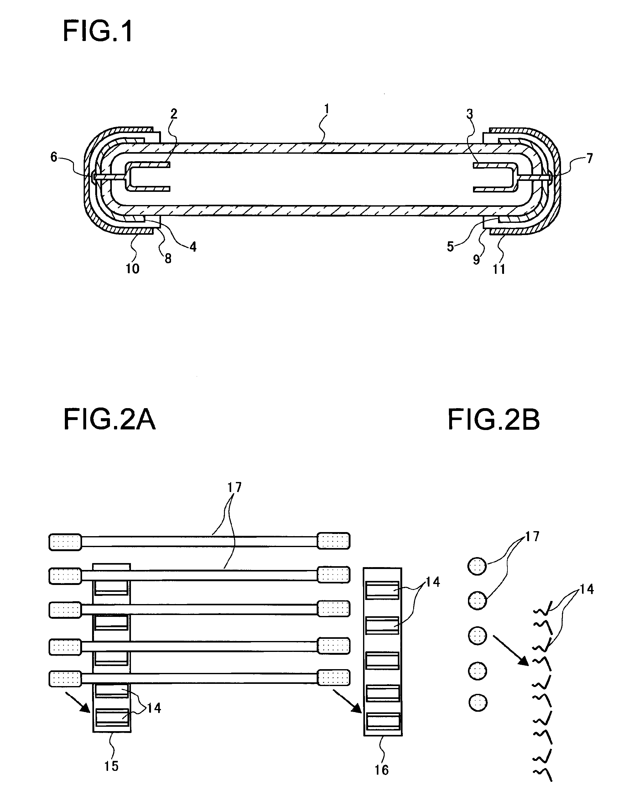
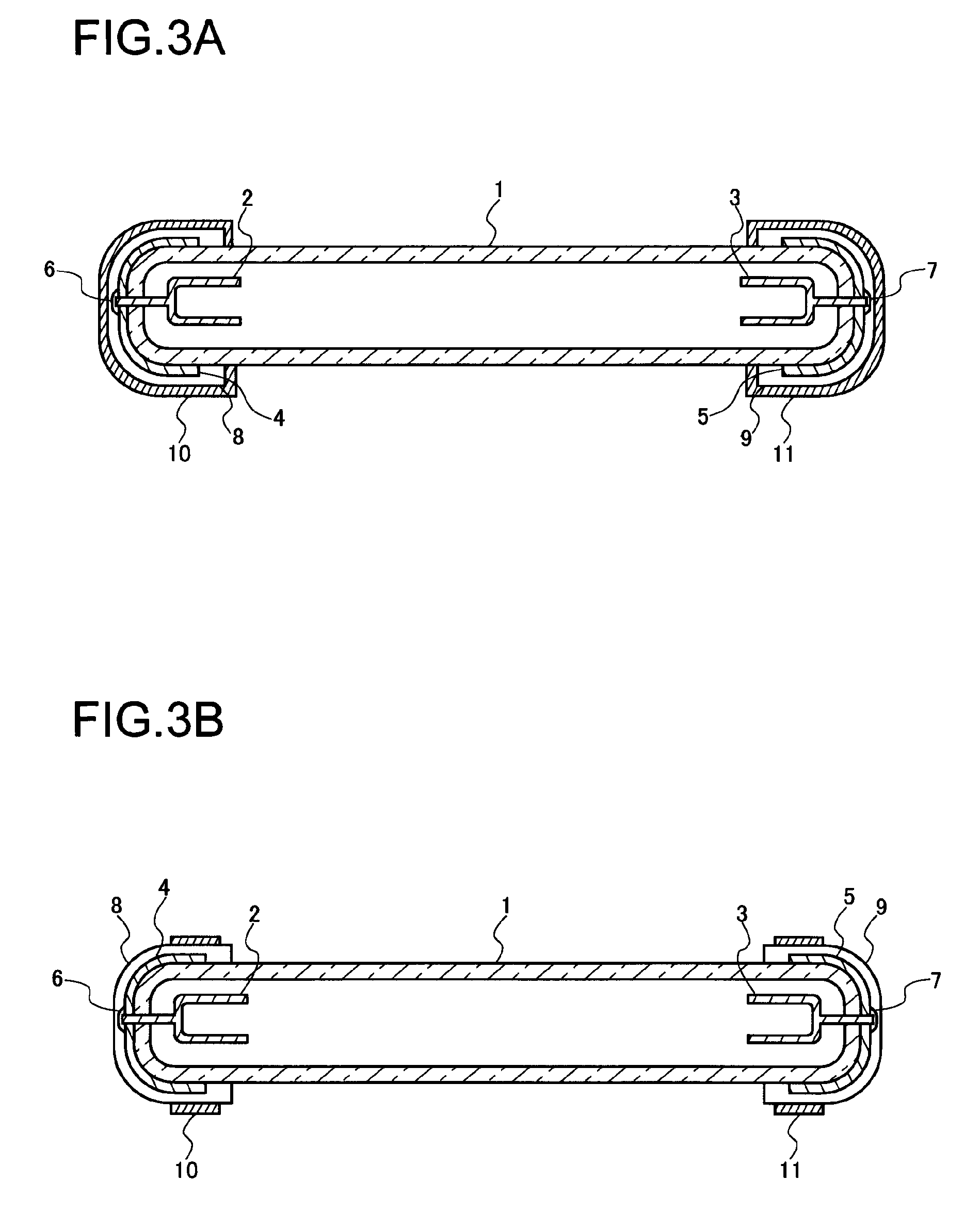
[0079]A schematic sectional view of a cold-cathode lamp according to a preferred embodiment of the present invention is shown in FIG. 1. In FIG. 1, such parts as find their counterparts in FIG. 14 are identified by common reference signs and their detailed description will not be repeated. In the cold-cathode lamp shown in FIG. 1, as compared with the conventional cold-cathode lamp shown in FIG. 14, external electrodes 4 and 5 are provided one at each end of the glass tube 1; the lead-out part of the internal electrode 2 and the external electrode 4 are soldered together with solder 6, and the lead-out part of the internal electrodes 3 and the external electrode 5 are soldered together with solder 7; insulating layers 8 and 9 are formed over the external electrodes 4 and 5 respectively; counter electrodes 10 and 11, each in the shape of a cylindrical cap, are formed on the insulating layers 8 and 9 respectively; the counter electrode 10 has a non-facing part not facing the external electrode 4, and the counter electrode 11 has a non-facing part not facing the external electrode 5; the gap between the non-facing portion of the counter electrode 10 and the glass tube 1 is filled by part of the insulating layer 8, and the gap between the non-facing portion of the counter electrode 11 and the glass tube 1 is filled by part of the insulating layer 9; the external electrode 4 does not have a non-facing portion not facing the counter electrode 10, and the external electrode 5 does not have a non-facing portion not facing the counter electrode 11. Specifically, the external electrodes 4 and 5 are formed of, for example, metal paste, metal foil, metal caps, or the like. The insulating layers 8 and 9 are formed of, for example, inorganic ceramic, resin, or the like. So long as satisfactory electrical connection is secured between a projection on the internal electrode 2 and the external electrode 4 and a projection on the internal electrodes 3 and the external electrode 5, the solder 6 and 7 may be omitted.
[0080]A display illumination device (an illumination device for a display device) according to a preferred embodiment of the present invention includes the cold-cathode lamp shown in FIG. 1, an illumination unit, and an optical sheet. The cold-cathode lamp shown in FIG. 1 is fitted to holding members provided on the front surface of the illumination unit, and the front surface of the illumination unit, having the cold-cathode lamp shown in FIG. 1 fitted on it, is then covered with the optical sheet.
[0081]How the cold-cathode lamp shown in FIG. 1 is fitted to the holding members is shown in FIGS. 2A and 2B, FIG. 2A being a front view and FIG. 2B a side view.
[0082]A plurality of pairs of holding members are provided on the front surface of the illumination unit, and one power supply (not illustrated) is provided on the rear surface of the illumination unit. The power supply outputs an alternating-current voltage of several tens of kHz. The holding members 14 provided in a front left-edge portion 15 of the illumination unit are connected together to one end of the power supply. The holding members 14 provided in a front right-edge portion 16 of the illumination unit are connected together to the other end of the power supply. The holding members 14 are formed of a resilient metal material (for example, spring steel), of which the resilience enables the holding members 14 to pinch in them the counter electrodes of the cold-cathode lamp shown in FIG. 1, thereby permitting the counter electrodes 10 and 11 of the cold-cathode lamp 17 structured as shown in FIG. 1 to be electrically connected to the holding members 14. With this structure, it is possible to connect the cold-cathode lamp shown in FIG. 1 and the power supply together without using harnesses (also called leads) and connectors.
[0083]In the cold-cathode lamp 17 structured as shown in FIG. 1 (hereinafter the “cold-cathode lamp 17”), a capacitor is formed by the external electrode 4 and the counter electrode 10 of the cold-cathode lamp 17, and another capacitor is formed by the external electrode 5 and the counter electrode 11 of the cold-cathode lamp 17. Thus, in terms of its equivalent circuit, the cold-cathode lamp 17 acts as a serial circuit including a resistor whose resistance decreases nonlinearly as the current through it increases and capacitors connected one to each terminal of the resistor, exhibiting, like the cold-cathode lamp shown in FIG. 17, a nonlinear positive impedance characteristic. Thus, when a plurality of cold-cathode lamps 17 are driven in parallel, they can all be lit. Moreover, in the cold-cathode lamp 17, since the internal and external electrodes are connected directly together, no additional parasitic capacitor or the like, as would be formed between harnesses (also called leads) and the electrically conductive casing of the illumination unit, appears between the resistor and the capacitor in the equivalent circuit. This makes it easy to suppress variations in lamp current among different cold-cathode lamps 17.
[0084]Moreover, in the cold-cathode lamp 17, charged particles do not collide with the portion of the inner wall surface of the glass tube facing away from the external electrodes, and thus there is no risk of pinholes being formed in the glass tube as in an external-electrode fluorescent lamp. In the cold-cathode lamp 17, charged particles do collide with and thereby wear (sputter) off the internal electrode, but, since the internal electrode is at an equal potential all over, charged particles reach, as on a lightning rod, a portion of the internal electrode near the discharge region on it, wearing it off there. As wear progresses, the portion of the internal electrode near the discharge region moves, preventing concentration of wear as in the external-electrode fluorescent lamp shown in FIG. 17. Thus the physical size of the internal electrode determines the operating life of the lamp.
[0085]Furthermore, in the cold-cathode lamp 17, a capacitor is formed by the external electrode 4 and the counter electrode 10 of the cold-cathode lamp 17, another capacitor is formed by the external electrode 5 and the counter electrode 11 of the cold-cathode lamp 17, and the counter electrodes 10 and 11 remain in fixed positions relative to the external electrodes 4 and 5. This stabilizes the capacitor formed by the external electrode 4 and the counter electrode 10 of the cold-cathode lamp 17 and the capacitor formed by the external electrode 5 and the counter electrode 11 of the cold-cathode lamp 17.
[0086]Now we will consider a cold-cathode lamp having counter electrodes 10 and 11 shaped differently from the cold-cathode lamp 17. A schematic sectional view of a cold-cathode lamp having counter electrodes 10 and 11 shaped differently from the cold-cathode lamp 17 is shown in FIG. 20. In FIG. 20, elements that find their counterparts in FIG. 1 are identified by common reference numerals and their detailed description will not be repeated.
[0087]In the cold-cathode lamp shown in FIG. 20, the lines of electric force produced by the electric charge on the external electrode 4 and the counter electrode 10 include not only those that rectilinearly connect the external electrode 4 and the counter electrode 10 but also those that take roundabout paths to reach the edge of the counter electrode 10. As a result, depending on the conditions of the voltage applied, the air layer near the edge of the counter electrode 10 may succumb to dielectric breakdown, causing corona discharge to occur near the edge of the counter electrode 10. If corona discharge occurs near the edge of the counter electrode 10, it may damage with heat the counter electrode 10 and the insulating layer 8, and may produce ozone, leading to poor reliability of the cold-cathode lamp. Likewise, in the cold-cathode lamp shown in FIG. 20, corona discharge may occur near the edge of the counter electrode 11.
[0088]In contrast, in the cold-cathode lamp 17, the counter electrode 10 has a non-facing portion not facing the external electrode 4; the counter electrode 11 has a non-facing portion not facing the external electrode 5; the gap between the non-facing portion of the counter electrode 10 and the glass tube 1 is filled by a portion of the insulating layer 8; the gap between the non-facing portion of the counter electrode 11 and the glass tube 1 is filled by a portion of the insulating layer 9; the external electrode 4 does not have a non-facing portion not facing the counter electrode 10; and the external electrode 5 does not have a non-facing portion not facing the counter electrode 11. This structure suppresses the lines of electric force taking roundabout paths to reach the edge of the counter electrodes 10 and 11, and thereby suppresses corona discharge near the edge of the counter electrodes 10 and 11, leading to higher reliability.
[0089]The shape of the counter electrodes 10 and 11 in the cold-cathode lamp 17 may be modified as in the cold-cathode lamp shown in FIG. 3A. In FIG. 3A, elements that find their counterparts in FIG. 1 are identified by common reference numerals and their detailed description will not be repeated. In the cold-cathode lamp shown in FIG. 3A, the counter electrodes 10 and 11 are shaped and arranged to completely cover the insulating layers 8 and 9 respectively. The shape of the counter electrodes 10 and 11 in the cold-cathode lamp 17 may be so modified as in the cold-cathode lamp shown in FIG. 3B. In FIG. 3B, elements that find their counterparts in FIG. 1 are identified by common reference numerals and their detailed description will not be repeated. In the cold-cathode lamp shown in FIG. 3B, the edge of the counter electrode 10 corresponds to the border between the non-facing portion (the portion that does not face the counter electrode 10) and the facing portion (the portion that faces the counter electrode 10) of the external electrode 4, and the edge of the counter electrode 11 corresponds to the border between the non-facing portion (the portion that does not face the counter electrode 11) and the facing portion (the portion that faces the counter electrode 11) of the external electrode 5. As a result, lines of electric force may take roundabout paths to reach near the edge of the counter electrode 10 corresponding to the border between the non-facing portion and the facing portion of the external electrode 4 and the edge of the counter electrode 11 corresponding to the border between the non-facing portion and the facing portion of the external electrode 5, causing corona discharge. Thus the cold-cathode lamp shown in FIG. 3B is less reliable than the cold-cathode lamp shown in FIG. 1. Even then, in the cold-cathode lamp shown in FIG. 3B, corona discharge does not occur near the non-facing portions of the counter electrodes 10 and 11, resulting in far higher reliability than the cold-cathode lamp shown in FIG. 20.
[0090]The counter electrodes 10 and 11 of the cold-cathode lamp 17 simply need to be electrically connected to the holding members 14. Preferably, to ensure electrical connection between the counter electrodes 10 and 11 of the cold-cathode lamp 17 and the holding members 14, ring-shaped projections10A and 11A may be provided on the counter electrodes 10 and 11 respectively so that, in the actually mounted state, the projections 10A and 11A make contact with the corresponding holding members 14.
[0091]Next, examples of arrangement of a power supply in a display illumination device according to a preferred embodiment of the present invention will be described. In the example of power supply arrangement shown in FIG. 5, the holding members provided in the front left-edge portion 15 of the illumination unit are connected together to one end of a power supply 18. Likewise, the holding members provided in the front right-edge portion 16 of the illumination unit are connected together to the other end of the power supply 18. The power supply 18 is disposed on the rear surface of the illumination unit, and outputs an alternating-current voltage of several tens of kHz. In the example of power supply arrangement shown in FIG. 6, the holding members provided in the front left-edge portion 15 of the illumination unit are connected together to one end of a power supply 19. On the other hand, the holding members provided in the front right-edge portion 16 of the illumination unit are connected together to one end of another power supply 20. The other end of the power supply 19 and the other end of the power supply 20 are grounded. The power supplies 19 and 20 are both disposed on the rear surface of the illumination unit, and each output an alternating-current voltage of several tens of kHz. The example of power supply arrangement shown in FIG. 6 requires shorter run lengths of the high-voltage lines 21 and 22 for feeding the high voltage, contributing to stabilization of the lamp current and reduction of power loss.
[0092]In a display illumination device according to a preferred embodiment of the present invention, from the perspective of reducing the number of power supplies needed, it is preferable that all its cold-cathode lamps be driven in parallel by a single power supply. Depending on the capacity of the power supply and the number of cold-cathode lamps, however, it is also possible, instead of driving all the cold-cathode lamps in parallel by a single power supply, to divide the cold-cathode lamps into a plurality of groups and provide as many power supplies, each driving the cold-cathode lamps within a group in parallel.
[0093]With respect to cold-cathode lamps electrically connected in parallel, the phase of the voltage fed to their internal electrodes at one side and the phase of the voltage fed to their internal electrodes at the other side may be made approximately 180 degrees out of phase with, so as to be inverted with respect to, each other. This structure makes laterally symmetric the brightness slope attributable to the leak current through a conductor (for example, the metal casing of the display illumination device) located near the power lines for parallel connection, contributing to enhanced illumination quality. Moreover, this structure, when the display illumination device described above is incorporated in a display device, makes practically zero the voltage that affects the display device (for example, the display device of a liquid crystal display panel) located near the power lines for parallel connection, making it possible to cancel the noise in the display device originating from the display illumination device.
[0094]In a case where a display illumination device according to a preferred embodiment of the present invention is applied to a display device with a display screen size over “37V”, to hold the discharge start voltage of cold-cathode lamps low, it is preferable that, in the display illumination device according to a preferred embodiment of the present invention, the cold-cathode lamps and the holding members be arranged, for example, as shown in FIG. 7 or 8.
[0095]In the example of cold-cathode lamp/holding member arrangement shown in FIG. 7, the front left-end portions of front left-side cold-cathode lamps 23 are pinched in holding members provided in a front left-edge portion 15; the front right-end portions of the front left-side cold-cathode lamps 23 are pinched in holding members provided in a first central portion 25; the front right-end portions of front right-side cold-cathode lamps 24 are pinched in holding members provided in a front right-edge portion 16; the front left-end portions of the front right-side cold-cathode lamps 24 are pinched in holding members provided in a second central portion 26.
[0096]In the example of cold-cathode lamp/holding member arrangement shown in FIG. 8, the front left-end portions of front left-side cold-cathode lamps 23 are pinched in holding members provided in a front left-edge portion 15; the front right-end portions of the front left-side cold-cathode lamps 23 are pinched in holding members provided in a first central portion 25; the front right-end portions of front right-side cold-cathode lamps 24 are pinched in holding members provided in a front right-edge portion 16; the front left-end portions of the front right-side cold-cathode lamps 24 are pinched in holding members provided in a second central portion 26. In addition, the glow region of the front right-side cold-cathode lamps 24 covers the first central portion 25, and the glow region of the front left-side cold-cathode lamps 23 covers the second central portion 26. As compared with the example of cold-cathode lamp/holding member arrangement shown in FIG. 7, the example of cold-cathode lamp/holding member arrangement shown in FIG. 8 suffers less drop of brightness in the first and second central portions 25 and 26.
[0097]In the examples of cold-cathode lamp/holding member arrangement shown in FIGS. 7 and 8, it is preferable that the surface layer of the front right-end portions (non-growing regions) of the front left-side cold-cathode lamps 23 and the surface layer of the front left-end parts (non-growing regions) of the front right-side cold-cathode lamps 24 be formed of a material with high reflectance. Moreover, a white material there helps alleviate uneven brightness in the first and second central portions 25 and 26. Thus, it is further preferable to use a white material with high reflectance.
[0098]Next, examples of arrangement of a power supply in the examples of cold-cathode lamp/holding member arrangement shown in FIGS. 7 and 8 will be described.
[0099]In the example of power supply arrangement shown in FIG. 9, the holding members provided in the front left-edge portion 15 of the illumination unit are connected together to one end of a power supply 27 and also to ground; the holding members provided in the front right-edge portion 16 of the illumination unit are connected together to one end of another power supply 28 and also to ground; the holding members provided in the first central portion 25 of the illumination unit and the holding members provided in the second central portion 26 of the illumination unit are connected together to the other end of the power supply 27 and also to the other end of the power supply 28. The power supplies 27 and 28 are both disposed on the rear surface of the illumination unit, and each output an alternating-current voltage of several tens of kHz; the power supplies 27 and 28 output, at their respective other ends, voltages of the same phase.
[0100]In the example of power supply arrangement shown in FIG. 10, the holding members provided in the front left-edge portion 15 of the illumination unit are connected together to one end of a power supply 29; the holding members provided in the front right-edge part 16 of the illumination unit are connected together to one end of another power supply 30; the holding members provided in the first central portion 25 of the illumination unit and the holding members provided in the second central portion 26 of the illumination unit are connected together to the other end of the power supply 29, also to the other end of the power supply 30, and also to ground. The power supplies 29 and 30 are both disposed on the rear surface of the illumination unit, and each output an alternating-current voltage of several tens of kHz; the power supplies 29 and 30 output, at their respective one ends, voltages of the same phase or of mutually inverted phases.
[0101]In the example of power supply arrangement shown in FIG. 11, the holding members provided in the front left-edge portion 15 of the illumination unit are connected together to one end of a power supply 31 and also to ground; the holding members provided in the front right-edge portion 16 of the illumination unit are connected together to the same end of the power supply 31 and also to ground; the holding members provided in the first central portion 25 of the illumination unit and the holding members provided in the second central portion 26 of the illumination unit are connected together to the other end of the power supply 31. The power supply 31 is disposed on the rear surface of the illumination unit, and outputs an alternating-current voltage of several tens of kHz.
[0102]The examples of power supply arrangement shown in FIGS. 9 to 11 all require shorter run lengths of the high-voltage lines for feeding the high voltage, contributing to stabilization of the lamp current and reduction of power loss.
[0103]As shown in FIGS. 12A to 12F, in a cold-cathode lamp according to a preferred embodiment of the present invention, part or all of the axis of its external electrode portion (the portion where the external electrode is formed on the glass tube) may be so bent as to be perpendicular or substantially perpendicular to the axis of its glow portion aligned in the main arrangement direction. With this structure, in a cold-cathode lamp according to a preferred embodiment of the present invention, with a view to increasing the capacitance of the capacitor including the counter electrode and the external electrode, the area of these can be increased without an undue increase in the width of the frame portion of a display illumination device.
[0104]The preferred embodiments described above deal with cases where a cold-cathode lamp according to the present invention is preferably provided with two external electrodes. Providing only one external electrode, however, suffices to obtain a nonlinear positive impedance characteristic. Thus, a cold-cathode lamp according to a preferred embodiment of the present invention may be provided with only one external electrode. For example, modifying the cold-cathode lamp according to a preferred embodiment of the present invention shown in FIG. 1 to have only one external electrode leads to a structure as shown in FIG. 13A. With the structure shown in FIG. 13A, however, the internal electrodes 3 side end portion of the lamp needs to be connected to a power supply via a harness (also called a lead) and a connector, and this makes the fitting and removal of the cold-cathode lamp troublesome. The preferred embodiments described above deal with cases where a cold-cathode lamp according to the present invention is preferably provided with two insulating layers. Providing only one insulating layer, however, suffices to obtain a nonlinear positive impedance characteristic. Thus, a cold-cathode lamp according to a preferred embodiment of the present invention may be provided with only one insulating layer. For example, modifying the cold-cathode lamp according to a preferred embodiment of the present invention shown in FIG. 1 to have only one insulating layer leads to a structure as shown in FIG. 13B. With the structure shown in FIG. 13B, the internal electrodes 3 side end portion of the lamp can be pinched in, by the resilience of, a holding member formed of a resilient metal material (for example, spring steel). This makes the fitting and removal of the cold-cathode lamp easy.
[0105]A display device according to another preferred embodiment of the present invention includes a display illumination device according to various preferred embodiments of the present invention as described above and a display panel. Among specific examples of display devices according to preferred embodiments of the present invention are transmissive liquid crystal display devices including as a backlight a display illumination device and having, on its front surface, a liquid crystal display panel.
[0106]Cold-cathode lamps according to various preferred embodiments of the present invention can be used as illumination sources provided in display illumination devices and as illumination sources provided in other various devices.
[0107]While preferred embodiments of the present invention have been described above, it is to be understood that variations and modifications will be apparent to those skilled in the art without departing the scope and spirit of the present invention. The scope of the present invention, therefore, is to be determined solely by the following claims.

PUM

no PUM

Description & Claims & Application Information

We can also present the details of the Description, Claims and Application information to help users get a comprehensive understanding of the technical details of the patent, such as background art, summary of invention, brief description of drawings, description of embodiments, and other original content. On the other hand, users can also determine the specific scope of protection of the technology through the list of claims; as well as understand the changes in the life cycle of the technology with the presentation of the patent timeline. Login to view more.

Similar technology patents

Stent

Owner:MANI INC +1

Buffered magazine method and system for loading and unloading ships

InactiveUS20060045659A1high reliabilitylittle impact
Owner:HUBBARD WILLIAM B SR

Aircraft assembly

ActiveUS20100224724A1not easily destroyhigh reliability
Owner:MITSUBISHI HEAVY IND LTD

Classification and recommendation of technical efficacy words

  • high reliability

Light-Emitting Device, Lighting Device, and Electronic Device

ActiveUS20110001146A1high reliability
Owner:SEMICON ENERGY LAB CO LTD

Radio communication scheme

InactiveUS7006465B2communication efficiency be improvehigh reliability
Owner:KK TOSHIBA

Semiconductor device and manufacturing method thereof

ActiveUS20060220114A1shorten channel-lengthshigh reliability
Owner:FUJITSU SEMICON LTD
Why Eureka
Try Eureka