Method and Device for Controlling a Suction Pressure of an Internal Combustion Engine

a technology of internal combustion engine and suction pressure, which is applied in the direction of position/direction control, combustion-air/fuel-air treatment, and fuel intakes, etc. it can solve the problems of increasing the operating cost of the vehicle, and expensive and complex parts of the exhaust gas turbocharger with variable geometry, etc. the effect of transmission and saving cabling

Active Publication Date: 2010-09-09
KNORR-BREMSE SYST FUER NUTZFAHRZEUGE GMBH
View PDF7 Cites 2 Cited by
  • Summary
  • Abstract
  • Description
  • Claims
  • Application Information

AI Technical Summary

Benefits of technology

[0017]In a further embodiment, the control unit is connected to measuring devices on the internal combustion engine which deliver data on, for example, pressure, mass flow rate, temperature, etc., which are significant not only for the control unit but also for the engine control device. The control unit can pass on these data to the engine control device to which it is connected, for example via a data bus. As a result, expenditure on cabling is saved, also allowing data to be transmitted more reliably.
[0018]By comparing the setpoint values which correspond to the current operating data with the current intake pressure values, the control unit adjusts the actuating element in order to reduce the cross section of the actuating section when the current intake pressure is too high. When the current intake pressure is too low, the actuating element is adjusted in order to increase the cross section of the actuating section. Simple regulation of the intake pressure of the internal combustion engine is therefore possible. An excessively high compressor pressure with an excessively high mass flow rate is easily reduced by making the cross section smaller through a corresponding, diminishing position of the actuating element which may be, for example, a flap.

Problems solved by technology

However, the exhaust gas turbocharger cannot deliver sufficient air in every operating state of the internal combustion engine and therefore generate a sufficient intake pressure.
However, it is disadvantageous here that an exhaust gas turbocharger with variable geometry is costly and complex in terms of parts.
Furthermore, it can be very maintenance-intensive, which increases the operating costs of a vehicle.
In addition, it is also not always possible for an exhaust gas turbocharger with variable geometry to deliver the quantity of air required by the internal combustion engine.
In particular in what is referred to as a non-steady-state range, such as for example acceleration, problems occur.
If the exhaust gas turbocharger is optimized for such a non-steady-state range, it has a poor efficiency and an associated high level of fuel consumption in the steady-state range, for example when travelling at a constant velocity or with a constant engine speed.
There is no description of controlling the intake pressure of an internal combustion engine, in particular at an excessively high compressor pressure of the exhaust gas turbocharger.
As a result, only a small amount of installation space is required.

Method used


Image

  • Method and Device for Controlling a Suction Pressure of an Internal Combustion Engine
  • Method and Device for Controlling a Suction Pressure of an Internal Combustion Engine
  • Method and Device for Controlling a Suction Pressure of an Internal Combustion Engine

Examples


Embodiment Construction

[0030]Identical components or functional units with the same function are characterized by the same reference symbols in the figures.

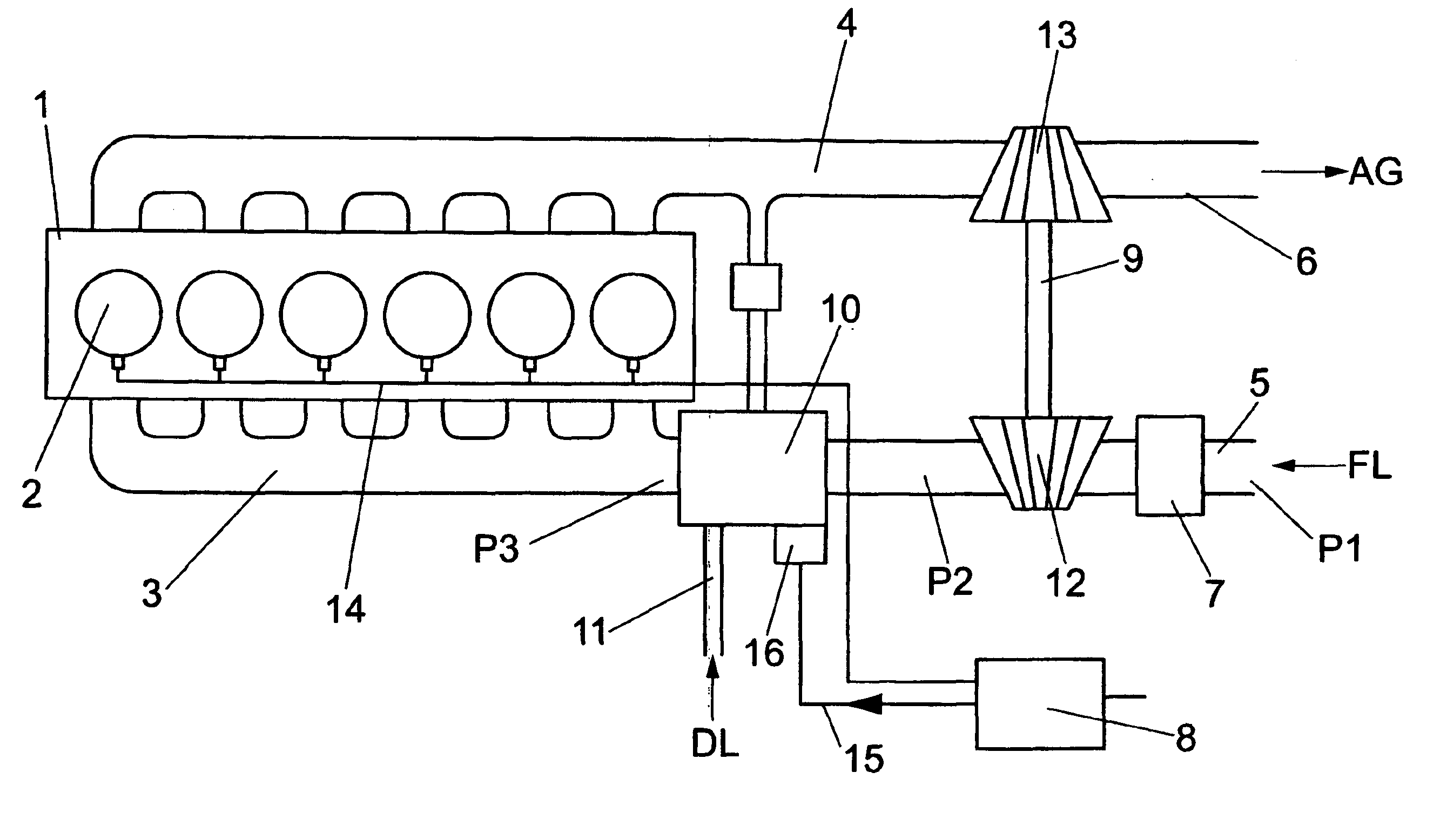
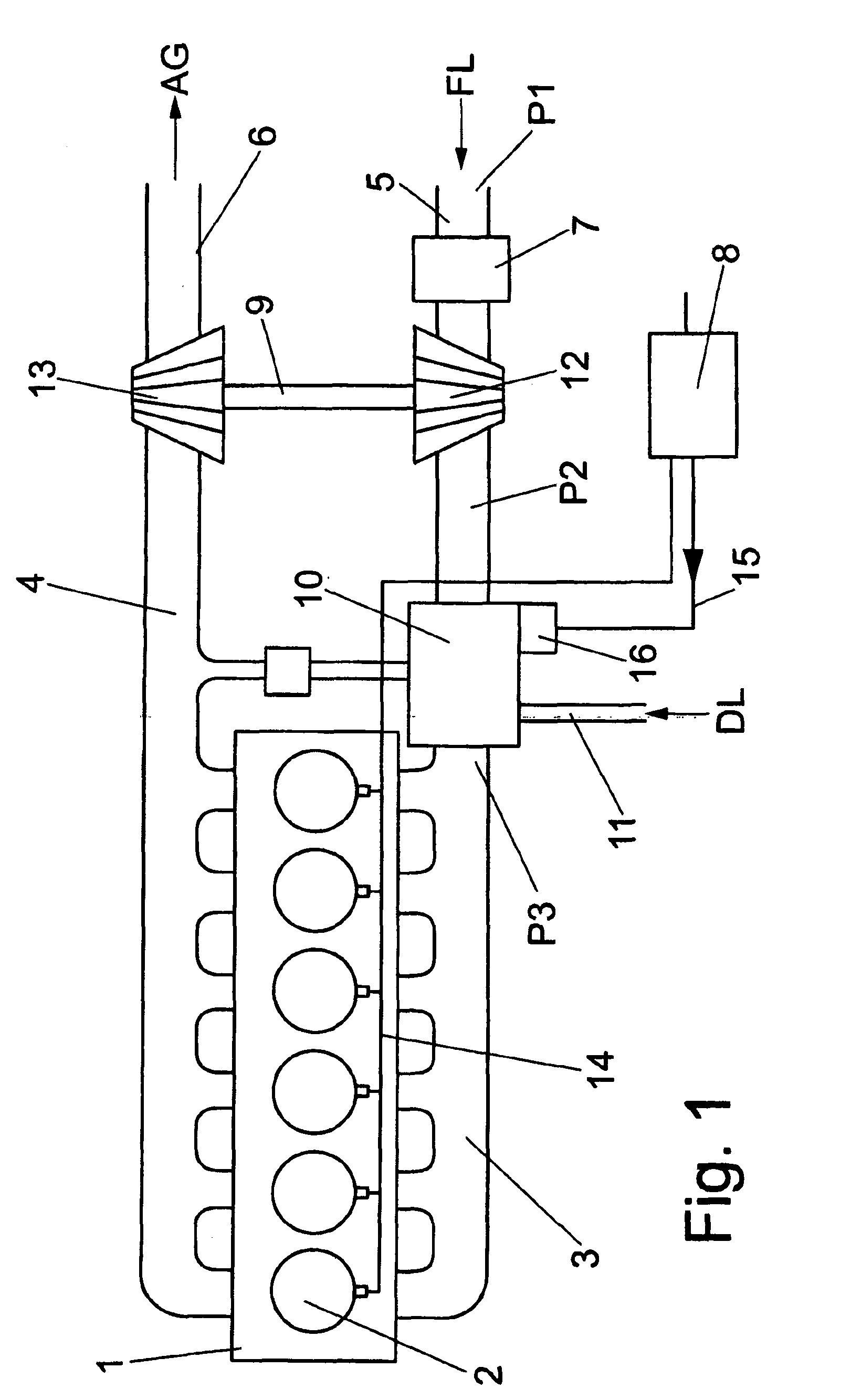
[0031]FIG. 1 shows a schematic illustration of an internal combustion engine 1 with an exhaust gas turbocharger 9 and a device according to the invention for regulating an intake pressure P3 in an intake line 3 of the internal combustion engine 1. The internal combustion engine 1 is, in this example, a diesel engine with six cylinders 2, the intake line 3 and an exhaust line 4. The intake line 3 is connected via an actuating section 10 to a compressor 12 of the exhaust gas turbocharger 9, which is connected via an air filter 7 to the air inlet 5 for fresh air FL at an inlet pressure P1. The compressor 12 of the exhaust gas turbocharger 9 is coupled to an exhaust gas turbine 13 which is arranged in the exhaust line 4 upstream of an exhaust gas outlet 6 for exhaust gas AG of the internal combustion engine 1 and is driven by the exhaust gas AG. The compre...


PUM


Abstract

A method device for controlling a suction pressure of an internal combustion engine, particularly a diesel engine having an exhaust gas turbocharger. The compressor is connected to a suction line of the internal combustion engine via an actuating section having an actuating element for changing a cross-section of the actuating section. In the first step, the current suction pressure in the suction line of the internal combustion engine is determined. A compressor pressure of the compressor is determined by pressure sensors and compared to the suction pressure. Values corresponding to current operating data of the internal combustion engine are identified and an actuation signal is generated using a controller, based on the comparison; and changing the cross-section of the actuating section is adjusted by adjusting the actuating element using the actuating signals.

Description

CROSS-REFERENCE TO RELATED APPLICATIONS[0001]This application is a continuation of PCT International Application No. PCT / EP2008 / 007764, filed Sep. 17, 2008, which claims priority under 35 U.S.C. §119 from German Patent Application No. DE 10 2007 045 622.2, filed Sep. 24, 2007, the entire disclosures of which are herein expressly incorporated by reference.BACKGROUND AND SUMMARY OF THE INVENTION[0002]The invention relates to a method and a device for regulating an intake pressure of an internal combustion engine, in particular diesel engine, having an exhaust gas turbocharger.[0003]Internal combustion engines, such as for example diesel engines, are frequently equipped with exhaust gas turbochargers. They have a turbine which is driven by the exhaust gas and which is coupled to a compressor. The compressor compresses the intake air in order to increase an intake pressure in an intake line for the internal combustion engine, as a result of which, for example, an acceleration behaviour ...

Claims


Application Information

Patent Timeline
Patent Type & Authority Applications(United States)
IPC IPC(8): F02D41/00F02M35/10
CPCF02D23/02F02D41/0007F02D41/10Y02T10/144F02D2200/0404F02D2200/0406F02D2041/0022Y02T10/12
Inventor GERUM, EDUARD
Owner KNORR-BREMSE SYST FUER NUTZFAHRZEUGE GMBH
Why Eureka
Try Eureka