Non-inserted nozzle for sterilizing or washing bottle container and method for sterilizing or washing inner surface of bottle container

a bottle container and nozzle technology, applied in the direction of disinfection, cleaning process and apparatus, cleaning using liquids, etc., can solve the problems of increasing the complexity and cost of the apparatus, the ratio of washing fluids to wetting the inner surface of the container is small, and the washing efficiency and sterilization efficiency can be improved. , the effect of reducing the number of times of sterilization

Active Publication Date: 2010-09-16
TOYO SEIKAN KAISHA LTD
View PDF1 Cites 15 Cited by
  • Summary
  • Abstract
  • Description
  • Claims
  • Application Information

AI Technical Summary

Benefits of technology

[0013]With the non-inserted nozzle in accordance with the present invention by forming and arranging the nozzle holes in the above-described manner, wetting of the inner surface of the container with the washing fluid or sterilizing fluid can be improved over that attained with the conventional spraying nozzles, the washing efficiency and sterilizing efficiency can be improved, and the washing fluid and sterilizing fluid can be saved. Furthermore, since the upper end surface of the nozzle mouth serves as a liquid-receiving surface, the reflux liquid that was obtained by spraying into the container, coming into contact with the inner wall surface of the container, flowing down, and discharging from the bottle mouth spreads over the liquid-receiving surface and flows out from the outer periphery of the liquid-receiving surface, but part of the reflux liquid directed toward the inner side of the liquid-receiving surface interferes with the sprayed fluid from the nozzle hole and is pushed up. As a result, the sprayed flow advances into the container in a state in which the diameter of the sprayed liquid flow is larger than that in the case of simple spraying from the nozzle holes. The sprayed liquid flow that advanced into the containers as a thickened flow interferes with part of the reflux liquid flowing down through the container mouth, thereby generating the juggling effect. Therefore, part of the reflux liquid flowing down from the container is supplied into the container again and can be make contribution to sterilization or washing and the washing fluid or sterilizing fluid can be saved accordingly. The juggling effect can be more effectively generated by forming a retention recess in the liquid-receiving surface. The juggling effect as referred to herein is an action of the sprayed liquid that pushes up and swings the reflux liquid up and down inside the bottle that is realized when a spraying nozzle is not inserted into the bottle, a liquid is sprayed from a plurality of nozzle holes onto the inner surface of the bottle, and the reflux liquid discharged from the bottle flows down along the bottle mouth and liquid-receiving surface of the nozzle, or is retained thereon. The larger is the juggling effect, the smaller is the amount of liquid required to provide the effective contact of the liquid with the entire inner surface of the bottle.
[0014]With the method for sterilizing and washing the inner surface of a container in accordance with the present invention, the non-inserted nozzle is disposed so as to be at a distance of 5 to 50 mm and below the mouth of a container conveyed in an inverted posture. Therefore, the washing fluid can be sprayed inside the container without inserting the spraying nozzle into the mouth of the container and removing it therefrom, it is not necessary to use a device for lifting the spraying nozzle, the sterilization time can be shortened, the number of drive components of the apparatus can be decreased, and the apparatus can be simplified and reduced in cost. Furthermore, since the upper end surface of the non-inserted nozzle serves as a liquid-receiving surface, the liquid discharged from the container can be discharged from a gap between the liquid-receiving surface and mouth end of the container. Moreover, due to the presence of the liquid-receiving surface, although the non-inserted nozzle is used, the juggling effect identical to that obtained with the inserted nozzle can be expected.

Problems solved by technology

The former washing method and washing nozzle of the above-described conventional technologies had a higher washing efficiency than a method by which the inside of a container was washed by simply spraying a columnar flow of a washing fluid inside the container and made contribution to saving the washing fluid, but because the spraying nozzle was inserted into the container mouth to spray the washing fluid, a lifting device for inserting a spraying nozzle into the mouth of the container was required, the complexity and cost of the apparatus were increased, time had to be ensured for inserting the spraying nozzle into the container mouth and removing the nozzle therefrom, processing speed could not be increased, and because the spraying nozzle was frequently raised and lowered, problems requiring solution were associated with endurance, maintenance, and inspection of the apparatus.
Furthermore, with simple spraying of the washing fluid, the ratio of washing fluid participated in wetting the inner surface of the container is small as compared with a large amount of required washing fluid and a problem requiring resolution is also associated with a large waste of the washing fluid.
However, because irregular oscillation of the atomized liquid flow are used to provide for uniform contact of the washing fluid with the inner surface of the container, there are intervals in which the washing liquid falls and periods in which the liquid does not fall on the bottom section of the container and the process lacks reliability.
Similar problems are also encountered when the inner surface of the container is sterilized.
As a result, this flow interferes with part of the reflux flow that flows down along the inner peripheral surface of the bottle mouth, thereby pushing up the reflux flow.

Method used


Image

  • Non-inserted nozzle for  sterilizing or washing bottle container and method for sterilizing or washing inner surface of bottle container
  • Non-inserted nozzle for  sterilizing or washing bottle container and method for sterilizing or washing inner surface of bottle container
  • Non-inserted nozzle for  sterilizing or washing bottle container and method for sterilizing or washing inner surface of bottle container

Examples


example 1

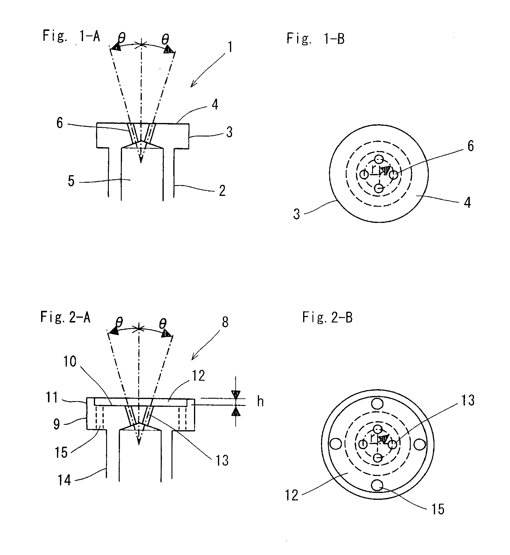
[0035]Two types of nozzles, which are a non-inserted nozzle (referred to hereinbelow as “A-type nozzle”) employing the nozzle mouth of the configuration shown in FIG. 1 and a non-inserted nozzle (referred to hereinbelow as “B-type nozzle”) employing the nozzle mouth of the configuration shown in FIG. 2 and having a retention wall were used. The washing nozzle had four nozzle holes 6, 13 formed with a pitch of 5 mm. The inclination angle θ of the nozzle holes 6, 13 and hole diameter D were varied as shown in Table 1 and the time required to wet the entire surface of the inner wall of a bottle was measured. The bottle containers used for the test were round PET bottles with a capacity of 500 mL and angular bottles with a capacity of 2000 mL. The top surface of the socket section of the washing nozzle and bottle was set to 15 mm. The test was conducted at three flow rates: 4 L / min, 4.5 L / min, and 5 L / min. The wetting state was estimated by using red water for the washing fluid and visu...

example 2

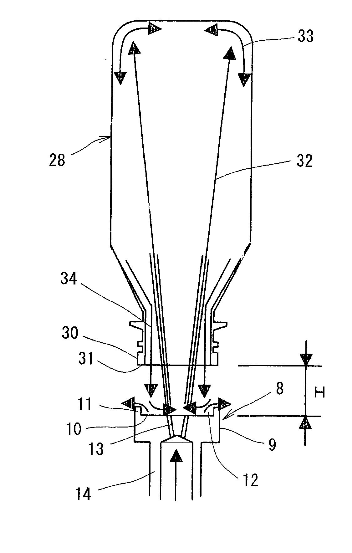
[0037]A liquid discharge state was studied by changing the distance in the washing test in order to study the effect of the distance H between the liquid-retaining surface of the non-inserted nozzle and the lower end surface of the container mouth. The results are shown in Table 2. The results demonstrated that the distance clearly affected the state of the liquid flowing down in this test; thus, the liquid discharge ability was poor when the distance H was less than 4 mm, and the interference with the falling reflux liquid was facilitated when the distance was 40 mm or more. In the case of this test example, it was confirmed that the appropriate distance H was 5 to 35 mm. However, the optimum distance H differs depending on the bottle mouth diameter and the range of the distance H increases with the increase in the mouth diameter.

Non-Inserted Nozzle Used: B-Type Nozzle

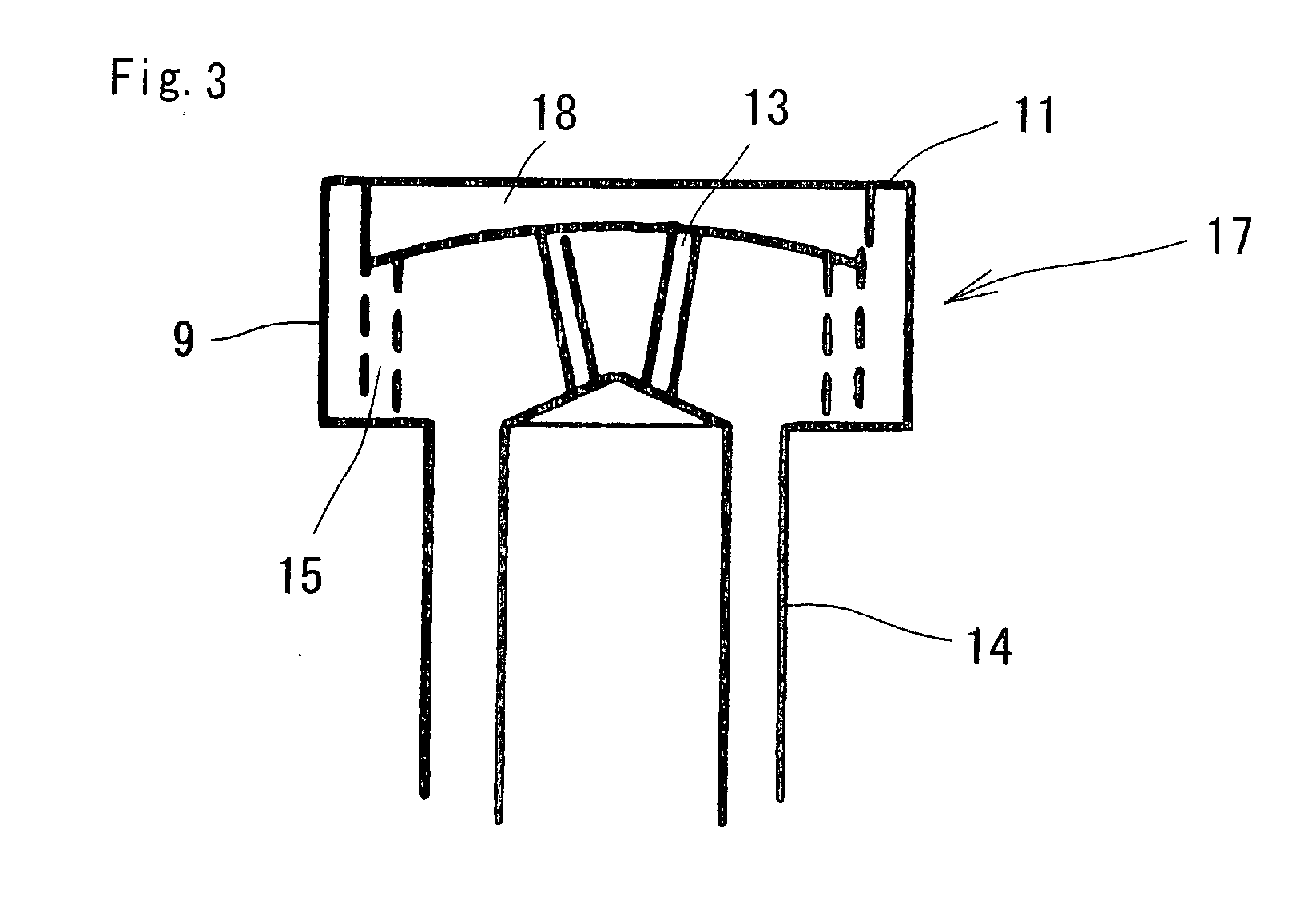
[0038]Four nozzle holes, inclination angle θ=5.0°, nozzle diameter D=1.5 mm, height of retention wall 4 mm. Supplie...

example 3

[0040]In order to verify the juggling effect of the B-type nozzle provided with a retention recess on the liquid-retaining surface, the non-inserted nozzles in which the number of nozzle holes, hole diameter, and height of retention wall differed as shown in Table 3 were used, a test was conducted three times on each nozzle by changing the spraying flow rate, and the time required to wet the entire inner surface of the container was measured. The distance between the liquid-retaining surface and the top surface of bottle mouth was set to 15 mm in all cases. The supplied bottles were 500 mL round PET bottles. The results are shown in Table 3.

TABLE 3TIMEREQUIREDDISTANCETO WETNUMBERHOLELIQUIDBETWEENTHE ENTIRENOZZLEOFANGLEDIAMETERRETAININGBOTTLE ANDFLOW RATESURFACE (sec)NUMBERHOLESθ (°)D (mm)RECESS (mm)NOZZLE (mm)BOTTLE(L / min)(1)(2)(3)EVALUATION*B-345.01.5215500 mL,3.51.62.02.2◯round41.91.81.5◯4.51.41.21.7◯B-445.01.5415500 mL,32.63.42.4Xround3.51.52.11.8◯41.11.31.1⊚B-565.01.2415500 mL,4...


PUM


Abstract

A non-inserted nozzle for washing a container that can increase the washing efficiency, decrease the amount of washing fluid used, and shorten the washing time in sterilizing and washing a bottle container. The upper end surface of a non-inserted nozzle 8 serves as a liquid-receiving surface 10, and a retention wall 11 of a predetermined height is formed on the outer periphery of the liquid-receiving surface, thereby producing a retention recess. A plurality of nozzle holes 13 linked to a fluid channel of a nozzle stem 14 are provided obliquely so as to spread outwardly substantially in the central section of the liquid-receiving surface. The non-inserted nozzle 8 is disposed below the mouth of an inverted container 28 at a distance H from it and the sterilizing fluid or washing fluid is sprayed from below the mouth of the container, without inserting the nozzle into the container.

Description

TECHNICAL FIELD[0001]The present invention relates to a non-inserted nozzle for sterilizing or washing a bottle container and to a method for sterilizing or washing the inner surface of a bottle container, and more particularly to a non-inserted nozzle for sterilizing or washing a bottle container (simply referred to hereinbelow as “container”) with the object of reducing the amount of sterilizing fluid or washing fluid used and conducting efficient bottle sterilization or washing, and to a method for sterilizing or washing the inner surface of a container, in particular to a non-inserted nozzle and a method for washing the inner surface of a container that are more advantageous for washing after sterilization.BACKGROUND ART[0002]A method by which containers are sterilized in an inverted state by using a sterilizing liquid such as an aqueous solution of peracetic acid has been widely used for sterilizing bottle containers in an aseptic loading system. The sterilization effect of the...

Claims


Application Information

Patent Timeline
Patent Type & Authority Applications(United States)
IPC IPC(8): B08B9/00
CPCA61L2/18A61L2/186A61L2/22A61L2202/15B08B9/34A61L2202/23B05B1/14B08B9/28A61L2202/17B08B9/093B65B55/06B08B3/02B65B55/10
Inventor NAGATANI, NOBUAKIIWASHITA, TAKESHIKOMINAMI, KENICHINAKAMORI, KEITA
Owner TOYO SEIKAN KAISHA LTD
Why Eureka
Try Eureka