Casting delivery nozzle

Inactive Publication Date: 2010-09-16
NUCOR CORP
View PDF30 Cites 7 Cited by
  • Summary
  • Abstract
  • Description
  • Claims
  • Application Information

AI Technical Summary

Benefits of technology

[0004]The present invention provides an apparatus and method for continuous thin strip casting that is capable of substantially reducing and inhibiting such defects in the cast strip, and at the same time reducing wear in the delivery nozzles and the costs in thin strip casting. By testing, we have found that a major cause of such strip defects is thinning of the shells during casting. It is believed that the thinning of the shells is caused by localized high volume flow causing washing away of the shells during formation. Such thinning of the shells can result in ridges in the cast strip. We have found by changing the delivery nozzle that the flow of molten metal into the casting pool can be made more even and closer to uniform. This improved flow from the delivery nozzle into the casting pool is particularly notable in the region where the casting pool meets the casting surfaces of the rolls, generally known as the “meniscus” or “meniscus regions” of the casting pool and provides more even flow of molten metal.
[0006]Australian Patent Application 60773 / 96 discloses a method and apparatus in which molten metal is delivered to the delivery nozzle in a trough closed at the bottom. Side openings are provided through which the molten metal flows laterally from the nozzle into a casting pool in the vicinity of the casting pool surface. The flow of molten metal into the casting pool was improved; however, unevenness in metal flow adjacent the casting roll surfaces caused washing away and thinning of the shells tending to cause defects in the cast strip. Further, there remained concern for wear on the delivery nozzle caused by the impact of the molten metal due to ferrostatic pressure, and turbulence caused as the molten metal moved through the delivery nozzle to discharge laterally into the casting pool below the meniscus of the casting pool. In addition, there was concern for extending the useful life of the delivery nozzles and in turn reducing the cost of producing thin cast strip.

Problems solved by technology

In prior art metal delivery nozzles, there has been a tendency to produce thin cast strip that contains defects from uneven solidification at the chilled casting surfaces of the rolls.
By testing, we have found that a major cause of such strip defects is thinning of the shells during casting.
It is believed that the thinning of the shells is caused by localized high volume flow causing washing away of the shells during formation.
Such thinning of the shells can result in ridges in the cast strip.
This localized heat loss near the side dams has a tendency to form “skulls” of solid metal in that region, which can grow to a considerable size and fall between the casting rolls and causing defects in the cast strip.
The flow of molten metal into the casting pool was improved; however, unevenness in metal flow adjacent the casting roll surfaces caused washing away and thinning of the shells tending to cause defects in the cast strip.
Further, there remained concern for wear on the delivery nozzle caused by the impact of the molten metal due to ferrostatic pressure, and turbulence caused as the molten metal moved through the delivery nozzle to discharge laterally into the casting pool below the meniscus of the casting pool.

Method used


Image

  • Casting delivery nozzle
  • Casting delivery nozzle
  • Casting delivery nozzle

Examples


Embodiment Construction

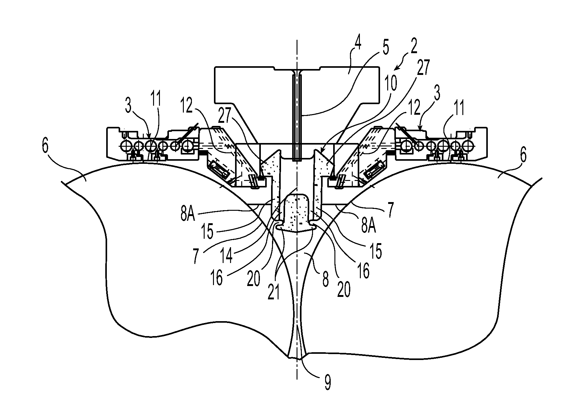
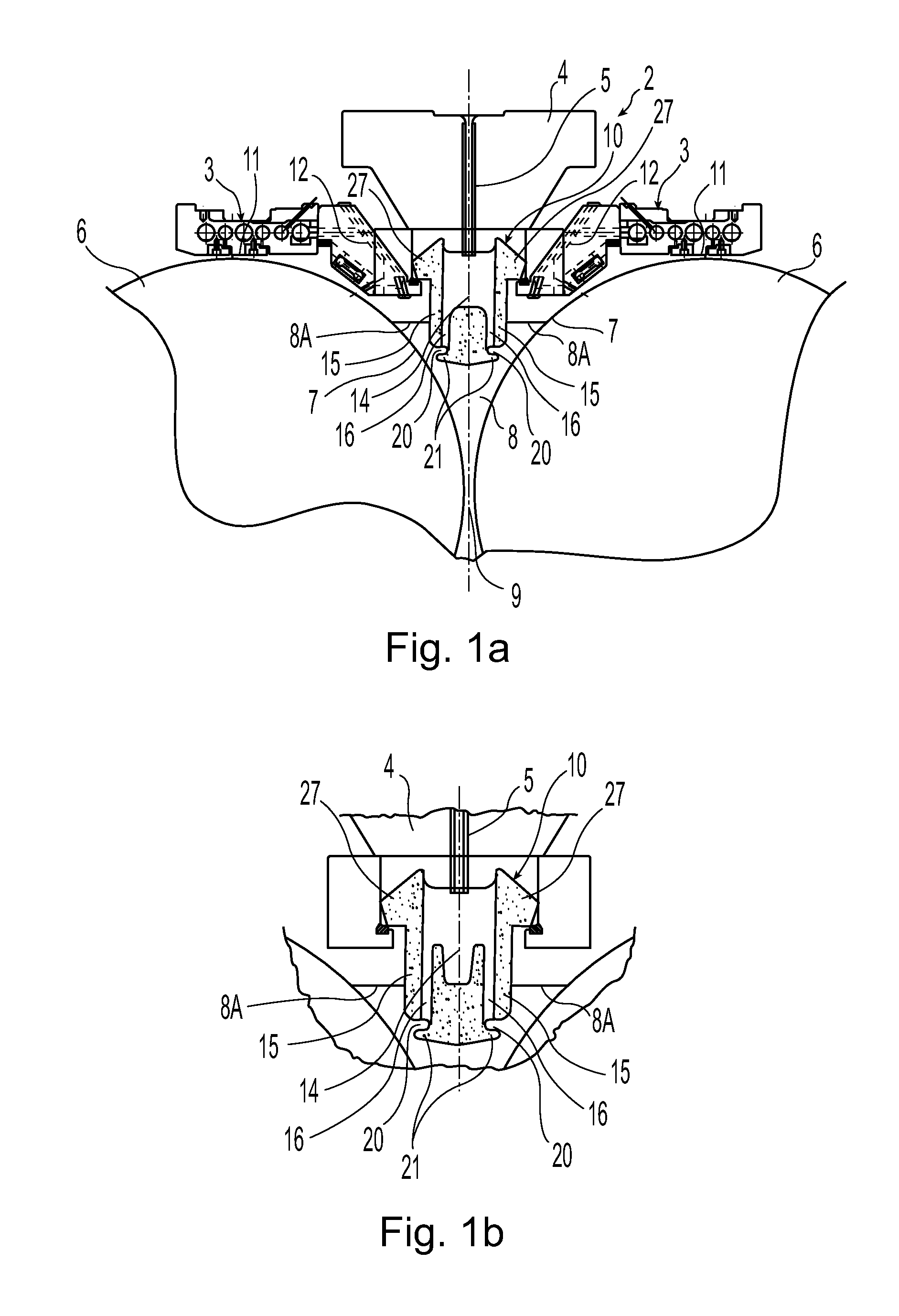
[0034]Referring to FIG. 1a, the metal strip casting apparatus 2 includes a metal delivery nozzle 10 formed in segments 13 located below a metal distributor 4 (also called a moveable tundish or transition piece) and above casting rolls 6. Casting rolls 6 are laterally positioned with nip 9 formed between them. Metal distributor 4 receives metal from a ladle through a metal delivery system (not shown) and delivers the molten metal to delivery nozzle 10. A shroud 5 may extend from metal distributor 4 and into delivery nozzle 10, for the purpose of transferring molten metal into the segments of delivery nozzle 10. In the alternative, metal distributor 4 may transfer metal to the segments of delivery nozzle 10 via a hole in the bottom of metal distributor 4. Below delivery nozzle 10, a casting pool 8 having surface 8A is formed supported on the casting surfaces 7 of casting rolls 6 adjacent nip 9. Casting pool 8 is constrained at the ends of the casting rolls by side dams or plates (not ...


PUM

PropertyMeasurementUnit
Flow rateaaaaaaaaaa

Abstract

A metal strip casting apparatus and method of casting continuous metal strip include assembling a pair of counter-rotatable casting rolls having casting surfaces positioned laterally forming a nip between for casting, and delivering molten metal through a delivery nozzle disposed above the nip to form a casting pool supported on the casting rolls. The delivery nozzle comprises at least one segment having a main portion and an end portion and an inner trough extending longitudinally through the main portion and into the end portion with end walls at opposite ends thereof, the inner trough communicating with outlets adjacent bottom portions formed in each segment adapted to deliver molten metal to a casting pool and the end portion having a reservoir portion having passages adapted to deliver molten metal to a casting pool.

Description

BACKGROUND AND SUMMARY[0001]This invention relates to making thin strip and more particularly casting of thin strip by a twin roll caster.[0002]It is known to cast metal strip by continuous casting in a twin roll caster. Molten metal is introduced between a pair of counter-rotating horizontal casting rolls which are cooled so that metal shells solidify on the moving roll surfaces, and are brought together at the nip between them to produce a solidified strip product delivered downwardly from the nip between the rolls. The term “nip” is used herein to refer to the general region at which the rolls are closest together. The molten metal may be poured from a ladle into a smaller vessel or tundish / distributor, from which it flows through a metal delivery nozzle located above the nip, which directs the molten metal to form a casting pool supported on the casting surfaces of the rolls above the nip. This casting pool is typically confined at the ends of the casting rolls by side plates or...

Claims


Application Information

Patent Timeline
IPC IPC(8): B22D11/06B22D11/00B22D37/00
CPCB22D11/0642B22D11/06
Inventor BOWMAN, BRIAN E.MAHAPATRA, RAMA BALLAVSCHUEREN, MIKEBLEJDE, WALTER N.
Owner NUCOR CORP
Why Eureka
Try Eureka