Line voltage dimmable constant current LED driver

a constant current, led technology, applied in the direction of instruments, light sources, electroluminescent light sources, etc., can solve the problems of repeated replacement costs, short life, increased energy costs, etc., to reduce power factor issues, reduce led on time, and avoid flicker

Inactive Publication Date: 2010-09-16
LED SPECIALISTS
View PDF17 Cites 132 Cited by
  • Summary
  • Abstract
  • Description
  • Claims
  • Application Information

AI Technical Summary

Benefits of technology

[0021]The driver circuit of the present disclosure uses a microcontroller to monitor the input power waveform to activate the LED output current when sufficient energy is available and to shut down the LED drive otherwise. This process follows the input power frequency of approximately 120 hz (rectified 60 Hz waveform). The microcontroller ensures that a load exists on the external dimmer when it is turning the driver off to aid the dimmer in operating consistently to avoid flicker and other performance issues. Thus, linear LED dimming is provided through pulse modulation of the LED current at the input waveform frequency. The microcontroller allows for future software programming adjustments to accommodate other types of dimmers and light engines.
[0022]Since the LED current driver is only on when there is enough energy on the input lines, large capacitors or other energy storage devices are not required. This saves on size and current draw is mostly in phase with input voltage thus reducing power factor issues (current embodiment has PF>0.70).
[0023]In one embodiment, the LED current driver incorporates a temperature compensation feature to control the LED engine power in relation to engine temperature to ensure it does not heat up beyond its design case temperature. In this embodiment, the LED current driver includes a temperature sensor that provides a real-time analog printed circuit board (PCB) temperature reading to the microprocessor. Depending on the host light engine design and light fixture application, the microprocessor can be programmed to reduce LED on time (i.e., effective power) in proportion to temperature. This enables the light engine to stay within its temperature design parameters to ensure long, reliable service life.

Problems solved by technology

First, incandescent light bulbs use a relatively large amount of power compared to other lighting products or technologies (e.g., light emitting diode (LED) or compact fluorescent lamp (CFL)) which increase energy costs.
Second, incandescent light bulbs have a relatively short life causing repetitive replacement costs.
Furthermore, since theses bulbs have a short life, labor costs in commercial applications will subsequently be effected by having maintenance personnel constantly replace the bulbs.
Because of their relatively low efficiency in generating light (95% or more energy is actually turned into heat with only 5% producing light), incandescent bulbs are actually being banned through government regulations at local and federal levels, in several countries around the world.
Compact fluorescent light (CFL) bulbs, while offering 2-3 times the energy efficiency over incandescent light bulbs, due to their design and light emission properties, can pose limitations in overall efficacy when combined with a light fixture.
In addition, CFL bulbs contain mercury (a long term environmental issue), are often slow to warm up to produce rated light levels and are generally not dimmable.
While LED technology is generally more expensive, there can be substantial savings in energy cost, bulb replacement and maintenance costs over a multi-year period.
Generally, these products have had relatively low light output to replace common light fixture incandescent sources (e.g. 75 W bulb) and poor thermal management properties required to ensure long LED life.
In addition, many of these light sources are highly directional and not compatible with many decorative light fixtures (e.g. pendants) detracting from the aesthetic appearance of the fixture and the LED light source.
Furthermore, it is difficult to control legacy light fixtures into which users will install these LED light engines.
Generally, LED light engines have heat sinks that require cooling via convective means or they can overheat and not perform to their design specifications for light output, efficacy or service life.

Method used


Image

  • Line voltage dimmable constant current LED driver
  • Line voltage dimmable constant current LED driver
  • Line voltage dimmable constant current LED driver

Examples


Embodiment Construction

[0035]Preferred embodiments of the present disclosure will be described hereinbelow with reference to the accompanying drawings. In the following description, well-known functions or constructions are not described in detail to avoid obscuring the invention in unnecessary detail.

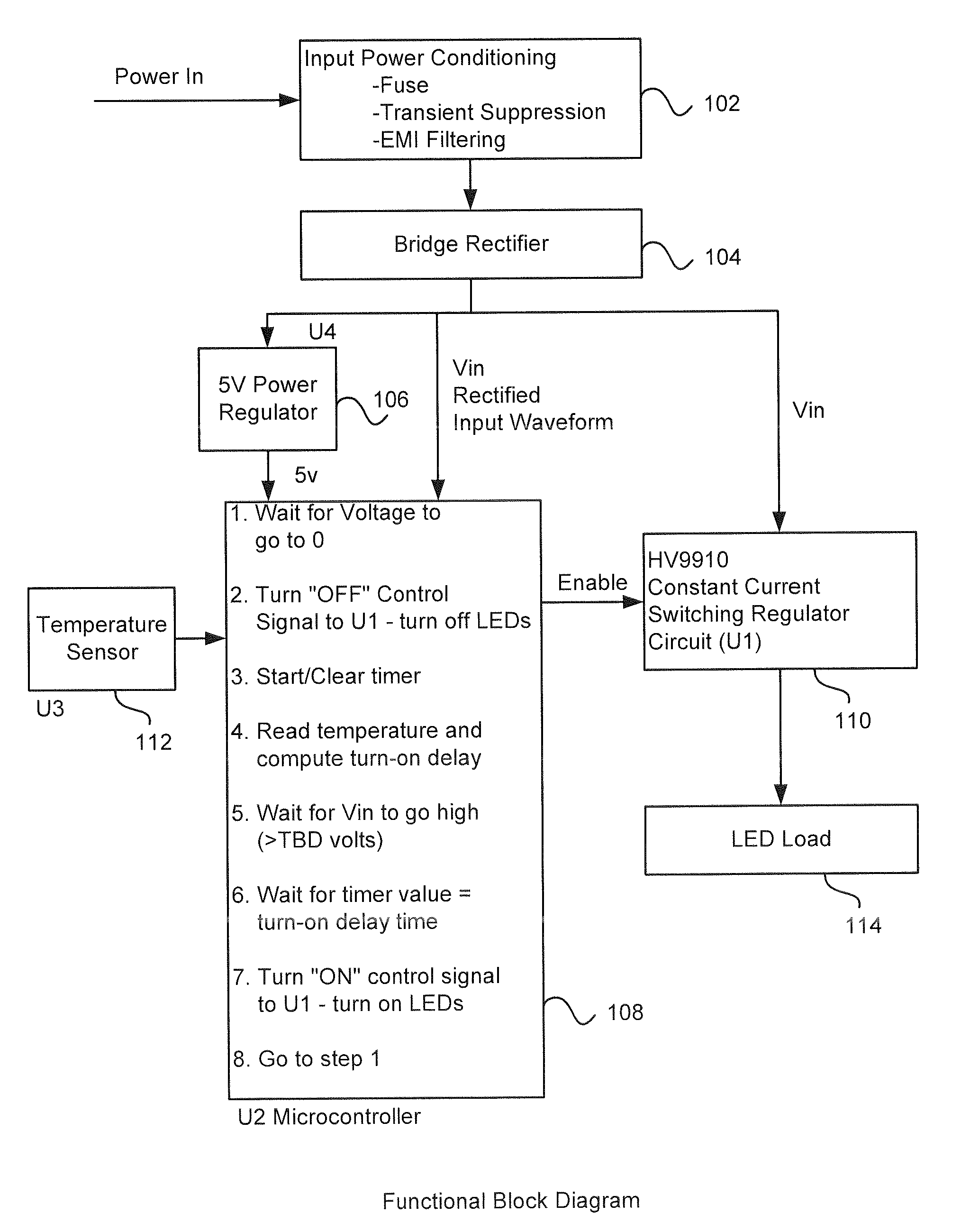
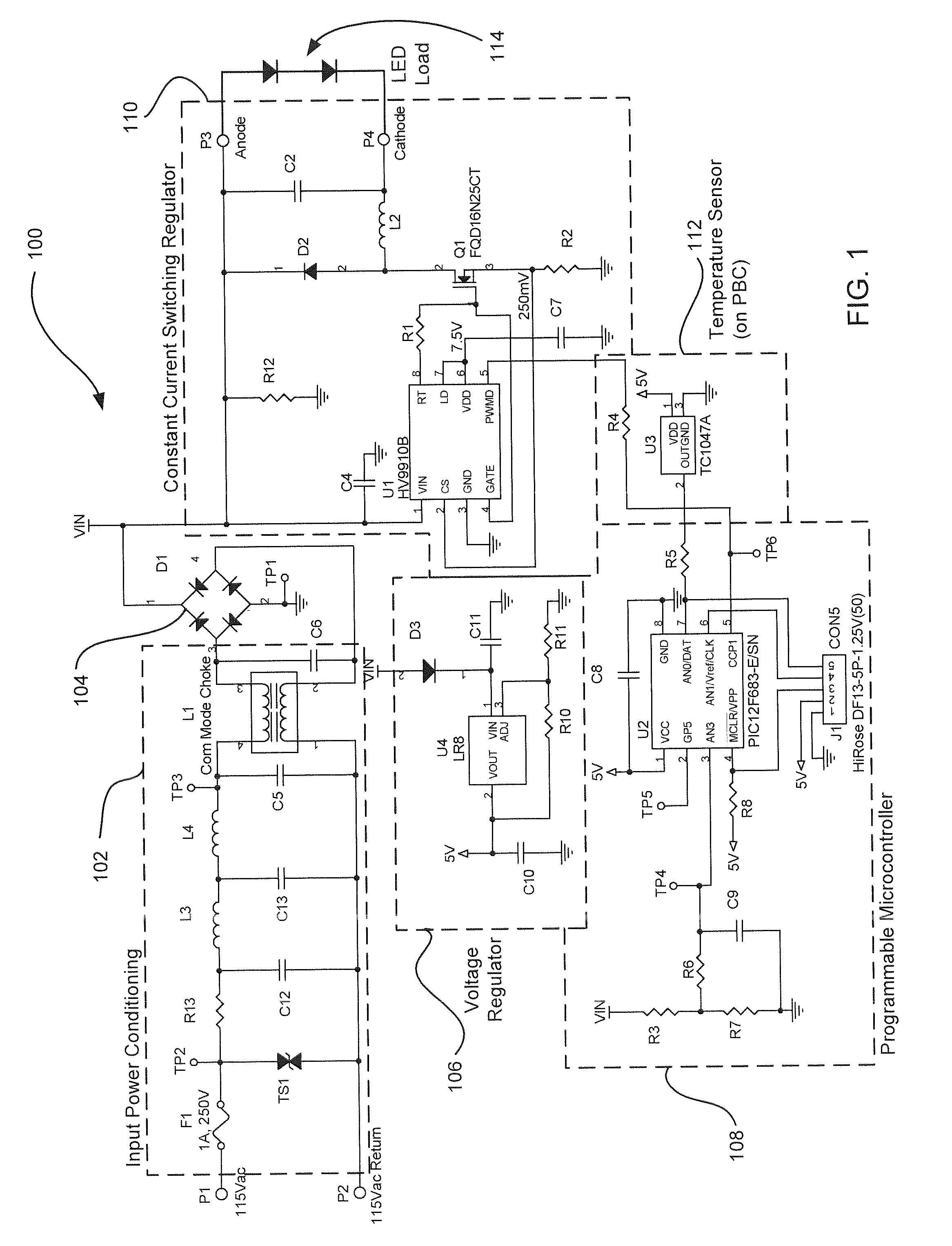
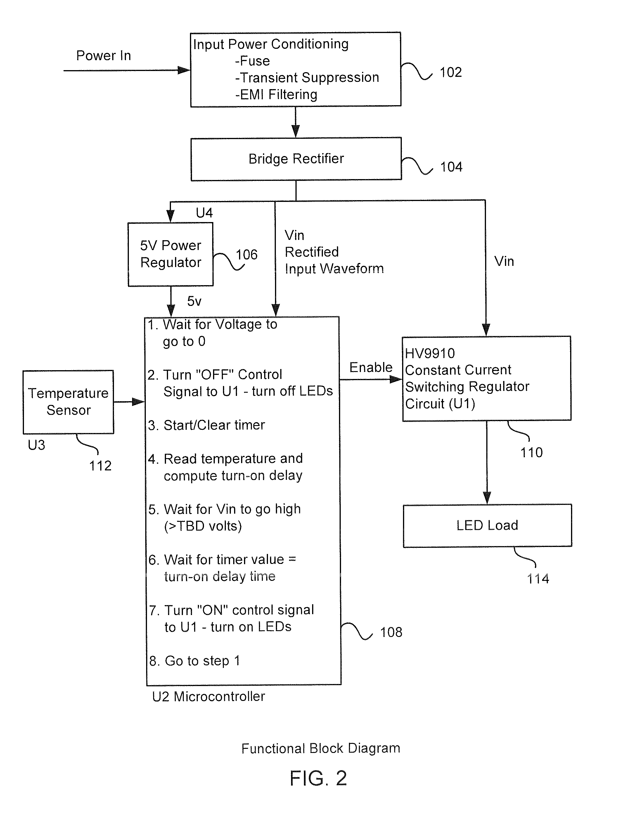
[0036]Referring to FIG. 1, an embodiment of a dimmable LED driver 100 of the present disclosure is shown. FIG. 2 provides a functional block diagram of the operation of the driver circuit 100 shown in FIG. 1.

[0037]Generally, the driver circuit 100 includes an input power conditioning section 102, a bridge rectifier 104, a voltage regulator 106, a programmable microcontroller 108 and a constant current switching regulator 110. A temperature sensor 112 is further provided for sensing the temperature of the driver circuit. The driver circuit 100 is coupled to and will drive LED load 114, i.e., at least one LED.

[0038]An input power waveform is illustrated in FIG. 3. The input power conditioning section 102 of th...


PUM


Abstract

A programmable LED constant current driver circuit for driving LEDs at constant current and dimming the LEDs using standard, off-the-shelf dimmers is provided. The current driver circuit of the present disclosure includes a temperature compensation feature which controls the on time for the LEDs based on a measured temperature of the current driver and associated circuits. In another embodiment, the current driver circuit is designed to receive a 24 VAC input and drive one or more LEDs in a transformer-based system dimming system.

Description

PRIORITY[0001]This application claims priority to U.S. Provisional Patent Appl. No. 61 / 159,865, filed Mar. 13, 2009, the contents of which are hereby incorporated by reference in its entirety.BACKGROUND[0002]1. Field of the Invention[0003]The present disclosure relates generally to lighting, light fixtures, lamp assemblies and LED lighting, and more particularly, to a programmable LED constant current drive circuit for driving LEDs at constant current and dimming the LEDs using standard, off-the-shelf, wall dimmers.[0004]2. Description of the Related Art[0005]Incandescent light bulbs are used in a large variety of lighting products. Although inexpensive to purchase, incandescent light bulbs have several drawbacks. First, incandescent light bulbs use a relatively large amount of power compared to other lighting products or technologies (e.g., light emitting diode (LED) or compact fluorescent lamp (CFL)) which increase energy costs. Second, incandescent light bulbs have a relatively s...

Claims


Application Information

Patent Timeline
Patent Type & Authority Applications(United States)
IPC IPC(8): H05B37/02
CPCH05B33/0848H05B33/0815H05B45/14H05B45/3725
Inventor REISENAUER, WILLIAMCANNARILI, KEVINSACKS, STEPHEN
Owner LED SPECIALISTS
Why Eureka
Try Eureka