
Power supply circuit, charging unit having the power supply circuit, and power supply method

Inactive Publication Date: 2010-09-16
RICOH ELECTRONIC DEVICES CO LTD
View PDF7 Cites 29 Cited by
  • Summary
  • Abstract
  • Description
  • Claims
  • Application Information

AI Technical Summary

Benefits of technology

[0013]Embodiments of the present invention may solve or reduce one or more of the above-described problems.
[0014]According to one embodiment of the present invention, there are provided a power supply circuit supplying power to a charge control circuit, a charging unit having the power supply circuit, and a method of supplying power to the charge control circuit in which one or more of the above-described problems may be solved or reduced.
[0015]According to one embodiment of the present invention, there are provided a power supply circuit supplying power to a charge control circuit capable of performing common constant-current, constant-voltage charging and improving charging efficiency; a charging unit having the power supply circuit; and a method of supplying power to the charge control circuit.
[0019]In a power supply circuit supplying power to a charge control circuit, a charging unit having the power supply circuit, and a method of supplying power to the charge control circuit according to one or more embodiments of the present invention, the voltage of a secondary battery is detected, and a predetermined first voltage input from a first direct-current power supply is converted into a voltage according to the detected voltage of the secondary battery and output to the charge control circuit. This makes it possible to perform common constant-current, constant-voltage charging on the secondary battery. Accordingly, it is possible to charge the lithium-ion battery, whose charging conditions are strict, with high accuracy, so that it is possible to supply the charge control circuit with a voltage that is the battery voltage of the secondary battery plus a required minimum voltage at the time of charging the secondary battery using a fuel cell or a solar battery. As a result, the power loss in the charge control circuit is significantly reduced, so that it is possible to improve charging efficiency.

Problems solved by technology

As a result, there has been a dramatic increase in the power consumption of portable electronic apparatuses.
On the other hand, portable electronic apparatuses that use lithium-ion batteries, which are satisfactory in terms of output (power) density but are short of energy density, can only operate for a short period of time.
Further, improvement in battery performance cannot keep pace with the increase in the power consumption of portable electronic apparatuses, so that the operating time of portable electronic apparatuses has failed to meet users' demands.
However, the output density of the fuel cell is too low to satisfy the demand of current portable electronic apparatuses.
However, the conventional charging unit using an AC adapter, which focuses more on shortening the charging time than on charging efficiency, does not have good charging efficiency.
This results in an extremely large power loss in the charge control circuit 140.
Thus, the charging efficiency of the conventional charging unit is not good.
Therefore, there is a problem in that the current bypass circuit wastes power after the secondary battery 165 is fully charged.
Further, the charging unit of FIG. 2 cannot perform constant-current, constant-voltage charging, which is commonly practiced as a lithium-ion battery charging method, and accordingly cannot perform charging with high accuracy.
Therefore, there is a problem in that the charging current may be excessively supplied if the voltage of the secondary battery 165 is low and that the voltage across the fully charged secondary battery 165 cannot be determined with accuracy.

Method used


Image

  • Power supply circuit, charging unit having the power supply circuit, and power supply method
  • Power supply circuit, charging unit having the power supply circuit, and power supply method
  • Power supply circuit, charging unit having the power supply circuit, and power supply method

Examples


first embodiment

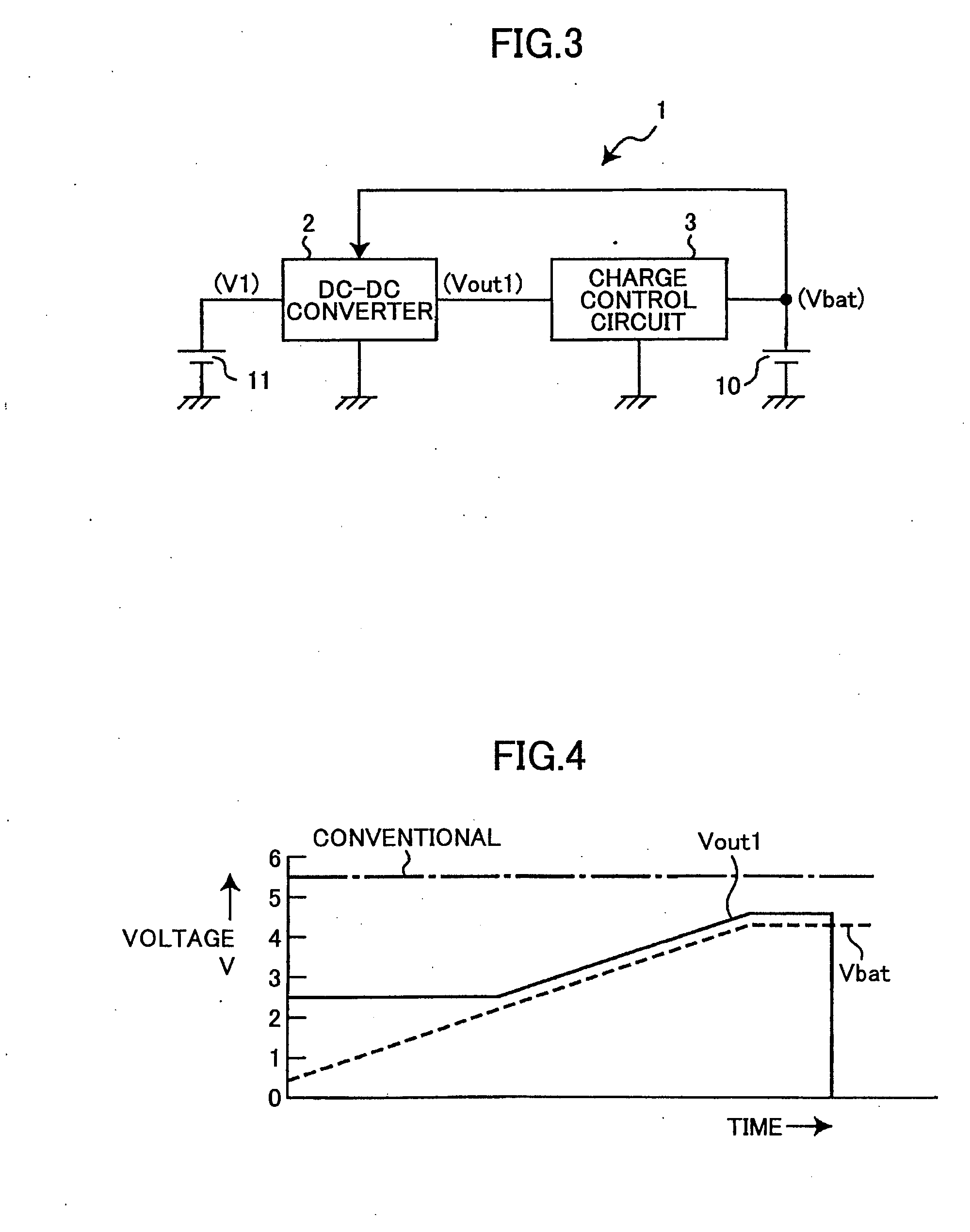
[0028]FIG. 3 is a schematic block diagram showing a charging unit 1 according to a first embodiment of the present invention.

[0029]Referring to FIG. 3, the charging unit 1, which charges a secondary battery 10 such as a lithium-ion battery, includes a DC-DC converter 2 such as a step-up switching regulator, a charge control circuit 3 that performs predetermined constant-current, constant-voltage charging on the secondary battery 10 using an output voltage Vout 1 output from the DC-DC converter 2, and a first direct-current (DC) power supply 11 formed of a battery such as a fuel cell or a solar battery. Hereinafter, the term “fuel cell” may also refer to a stack of fuel cells.

[0030]A first voltage V1 is input to the DC-DC converter 2 from the first DC power supply 11. The DC-DC converter 2 increases the first voltage V1 so that the first voltage V1 is proportional to a battery voltage Vbat, for example, greater than the battery voltage Vbat by a predetermined value, and outputs the i...

second embodiment

[0038]In the first embodiment, power is supplied to the DC-DC converter 2 only from the first DC power supply 11. Alternatively, according to a second embodiment of the present invention, power may be supplied from two DC current sources, that is, a first DC current source and a second DC current source, to the DC-DC converter, and the supply voltage from the first DC power supply may be increased and supplied to a charge control circuit when the supply voltage from the second DC power supply becomes lower than a predetermined value.

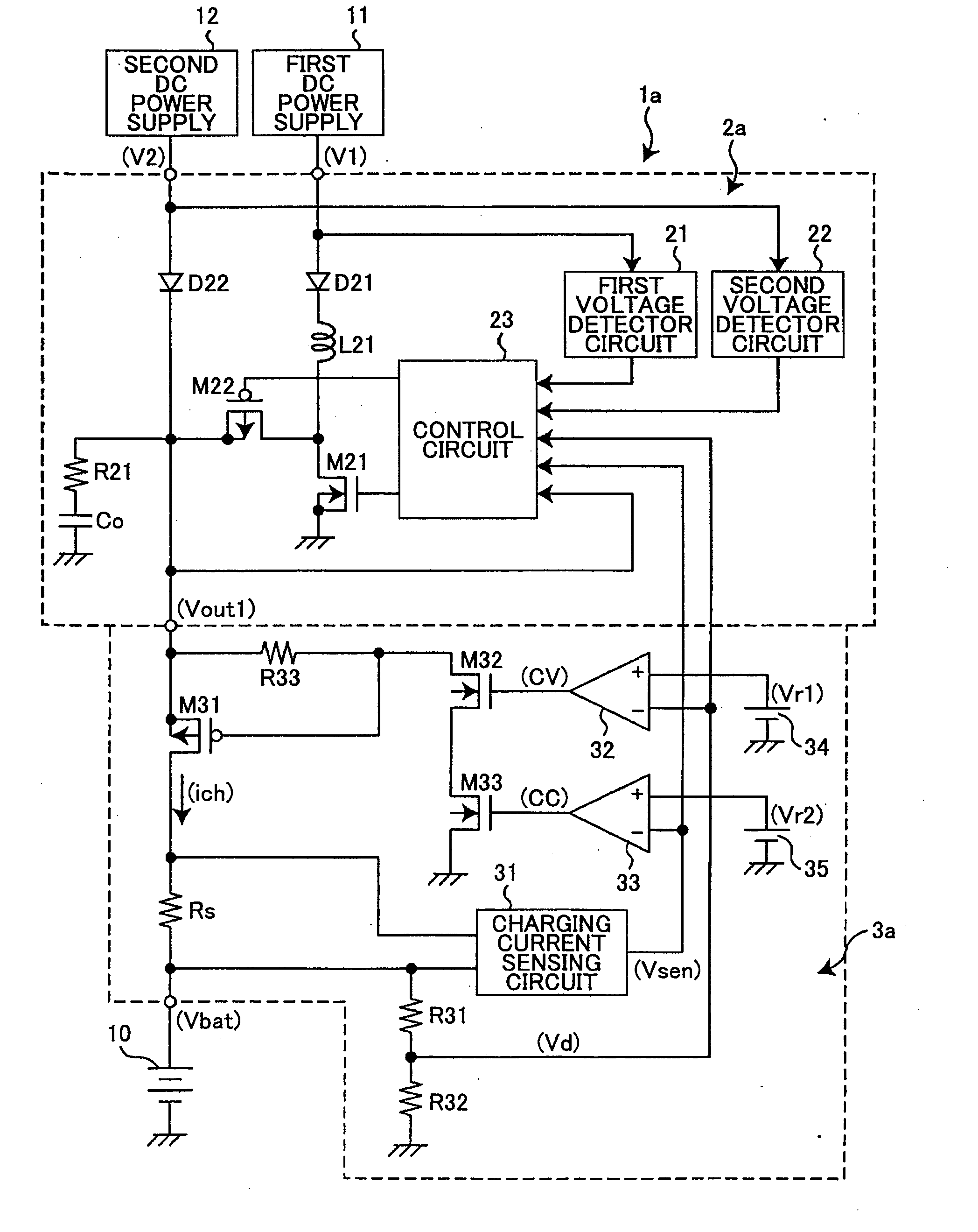
[0039]FIG. 5 is a circuit diagram showing a charging unit 1a according to the second embodiment of the present invention. In FIG. 5, the same elements as those of FIG. 3 are referred to by the same reference numerals.

[0040]Referring to FIG. 5, the charging unit 1a, which charges the secondary battery 10 such as a lithium-ion battery, includes a DC-DC converter 2a forming a step-up switching regulator, a charge control circuit 3a that performs predetermin...

third embodiment

[0059]In the above-described second embodiment, the DC-DC converter 2a does not perform output control of the second voltage V2 and only controls the operation of increasing the first voltage V1. Alternatively, according to a third embodiment of the present invention, the DC-DC converter may control output of the second voltage V2 to the charge control circuit 3a in accordance with the value of the second voltage V2.

[0060]FIG. 6 is a circuit diagram showing a charging unit 1b according to the third embodiment of the present invention. In FIG. 6, the same elements as those of FIG. 5 are referred to by the same reference numerals, and a description thereof is omitted.

[0061]There is a difference between FIGS. 5 and 6 in that a PMOS transistor M41 that controls output of the second voltage V2 to the charge control circuit 3a in accordance with the detection result of the second voltage V2 by the second voltage detector circuit 22 is added in FIG. 6.

[0062]Referring to FIG. 6, the chargin...


PUM


Abstract

A power supply circuit supplying power to a charge control circuit charging a secondary battery is disclosed. The power supply circuit includes a direct-current power supply configured to generate and output a predetermined voltage; and a DC-DC converter configured, to detect the voltage of the secondary battery, convert the predetermined voltage input from the direct-current power supply into a voltage according to the detected voltage of the secondary battery, and output the converted voltage to the charge control circuit.

Description

TECHNICAL FIELD[0001]The present invention relates generally to power supply circuits supplying power to a charge control circuit charging a secondary battery, charging units having the power supply circuits, and methods of supplying power to the charge control circuit, and more particularly to a power supply circuit supplying power to a charge control circuit capable of performing charging with high efficiency even in the case of using a power generation element such as a fuel cell or a solar cell as a power supply, a charging unit having the power supply circuit, and a method of supplying power to the charge control circuit.BACKGROUND ART[0002]Secondary batteries, in particular lithium-ion batteries recently, are often used in portable electronic apparatuses for reasons of economics, convenience, and power output density.[0003]Further, the applications of portable electronic apparatuses are ever increasing, and terrestrial digital broadcasting, so-called one-segment broadcasting, ...

Claims


Application Information

Patent Timeline
IPC IPC(8): H02J7/04
CPCH01M10/44H01M16/006H02J7/0054H02J2007/0059H02J7/0077H02J7/025H02J7/0055H02J2207/40H02J2207/20H02J7/342H02J7/00712Y02E60/50Y02E60/10H02J50/10H02J7/0049H02J7/02H02J5/00
Inventor NODA, IPPEI
Owner RICOH ELECTRONIC DEVICES CO LTD
Features
  • Generate Ideas
  • Intellectual Property
  • Life Sciences
  • Materials
  • Tech Scout
  • Unparalleled Data Quality
  • Higher Quality Content
  • 60% Fewer Hallucinations
Learn More