Plotting state adjusting method and device

Inactive Publication Date: 2010-09-16
FUJIFILM CORP
View PDF3 Cites 7 Cited by
  • Summary
  • Abstract
  • Description
  • Claims
  • Application Information

AI Technical Summary

Benefits of technology

[0006]It is a general object of the present invention to provide a recording state adjusting method and device for reliably reducing jaggies produced on an image pattern when the image pattern is recorded on a recording medium by a plurality of image recording elements that are disposed i

Problems solved by technology

When multiple exposure is performed by the inclined DMD, if the direction of the array of exposed points formed on the recording medium by closely located micromirrors is close to the direction of an image pattern to be recorded on the recording medium, then jaggies tend to be produ

Method used


Image

  • Plotting state adjusting method and device
  • Plotting state adjusting method and device
  • Plotting state adjusting method and device

Examples


Embodiment Construction

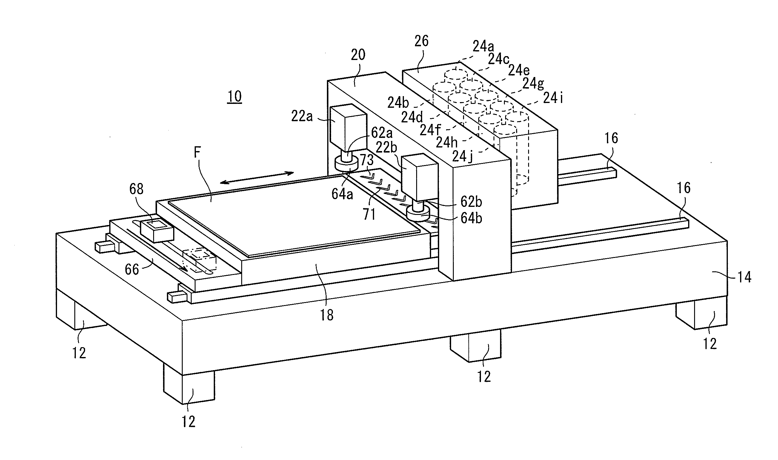
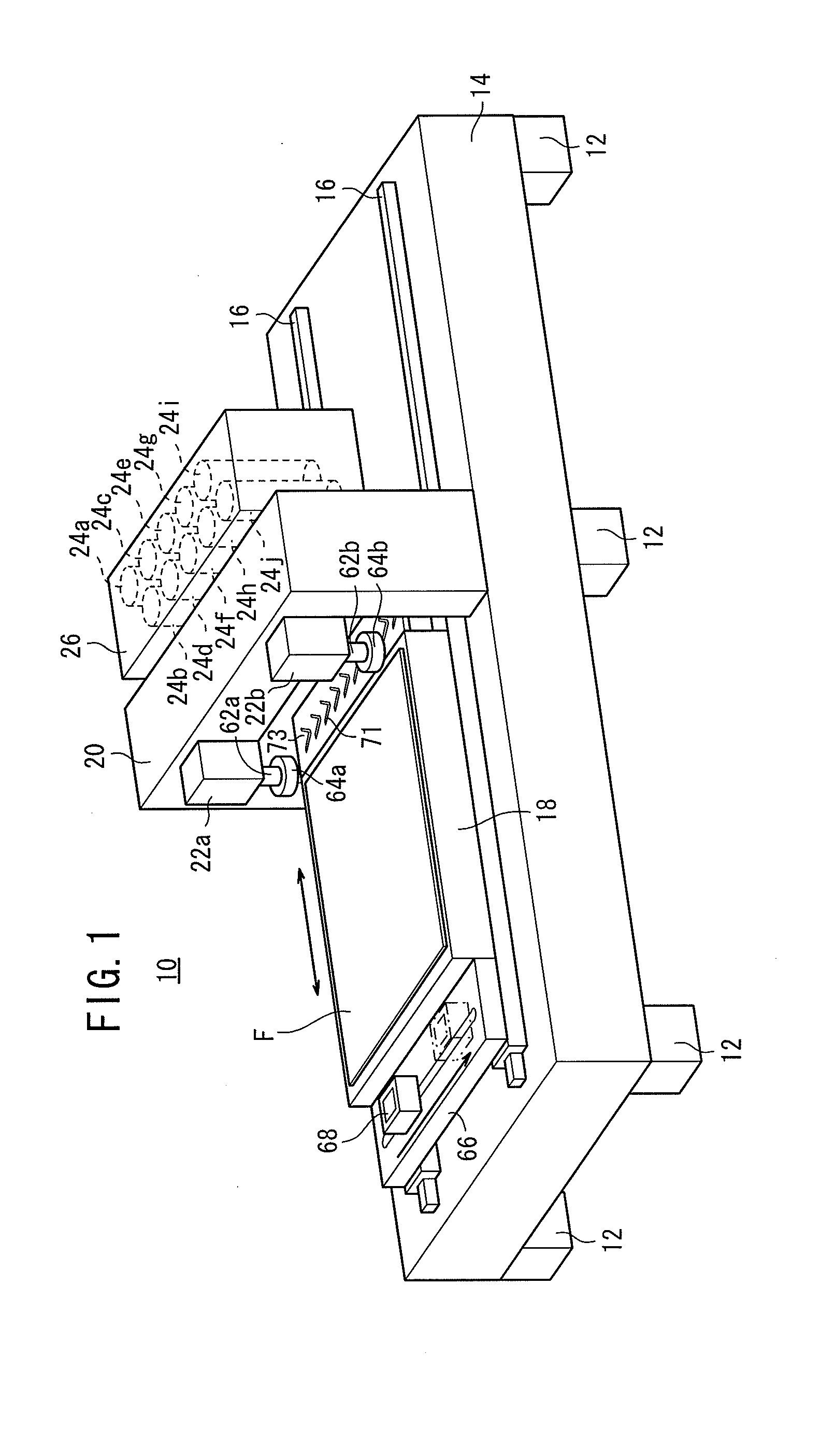
[0032]FIG. 1 shows an exposure apparatus 10 of the flat-bed type as a recording device to which a recording state adjusting method and device according to the present invention is applied. The exposure apparatus 10 has a bed 14 supported by a plurality of legs and which hardly deforms and an exposure stage 18 mounted on the bed 14 by two guide rails 16 for reciprocal movement therealong in the directions indicated by the arrow. A substrate F coated with a photosensitive material is attracted to and held by the exposure stage 18.

[0033]A portal-shaped column 20 is disposed centrally on the bed 14 over the guide rails 16. CCD cameras 22a, 22b are fixedly mounted on one side of the column 20 for detecting the position where the substrate F is mounted on the exposure stage 18. A plurality of exposure heads 24a through 24j for recording an image on the substrate F through exposure are positioned in and held by a scanner 26 that is fixedly mounted on the other side of the column 20. The ex...


PUM


Abstract

It is possible to set an optical magnification capable of making a recording position shift amount with respect to Y direction of the plotting point formed by a micro mirror within an allowance range from the relationship between a Y-direction distance between mirror images obtained by projecting micro mirrors constituting a DMD onto a substrate, an inclination angle of the DMD, an image pattern recording pitch, and an optical magnification.

Description

TECHNICAL FIELD[0001]The present invention relates to a recording (plotting) state adjusting method and device in an image recording apparatus for relatively moving a plurality of recording elements arrayed in a two-dimensional array in a predetermined scanning direction along a recording surface and controlling the recording elements according to recording data to record an image on the recording surface.BACKGROUND ART[0002]Heretofore, there have been proposed various exposure apparatus, as an example of recording apparatus, having a spatial light modulator such as a digital micromirror device (DMD) or the like for exposing a recording medium to an image with a light beam modulated with image data. The DMD is a mirror device comprising a number of micromirrors for changing the angles of their reflecting surfaces depending on control signals based on image data, the micromirrors being arranged in a two-dimensional array on a semiconductor substrate such as of silicon or the like. An...

Claims


Application Information

Patent Timeline
IPC IPC(8): H04N1/04
CPCG01D1/00G01D15/00G01D21/00G03F7/70791H04N1/0473H04N1/1008H04N2201/04763H04N1/19505H04N1/19573H04N2201/04713H04N2201/0472H04N2201/04744H04N1/113G03F7/2051G03F7/70391
Inventor KINJO, NAOTOSUMI, KATSUTOKITANO, RYO
Owner FUJIFILM CORP
Why Eureka
Try Eureka