Method and apparatus for allocating backhaul transmission resource in wireless communication system based on relay

a wireless communication system and transmission resource technology, applied in the field of wireless communication system wireless relay, can solve problems such as switching time delay at relay nodes, and achieve the effects of minimizing influence on conventional systems, avoiding overlap, and better using wireless backhaul resources

Active Publication Date: 2010-09-16
SAMSUNG ELECTRONICS CO LTD
View PDF17 Cites 51 Cited by
  • Summary
  • Abstract
  • Description
  • Claims
  • Application Information

AI Technical Summary

Benefits of technology

[0015]Another aspect of the present invention is to provide uplink and downlink backhaul sub-frame structures which may reduce a time delay in an RF transmission / reception switching when employing an L3 relay and may be compatible with conventional uplink and downlink sub-frame structures.
[0024]Therefore, aspects of this invention do not only eliminate an overlap of transmission and reception timing in a relay node due to an RF transmission / reception switching time delay, but also make better use of wireless backhaul resources and minimize an influence on conventional systems by offering the compatibility with conventional uplink and downlink sub-frame structures.

Problems solved by technology

Normally signal distortion due to a path loss of a channel is one of critical restrictions in high-rate data transmission under limited resources.
If a wireless relay node simultaneously performs signal reception and transmission, a transmitted signal may often act as interference to a received signal.
Unfortunately, this may cause a switching time delay at a relay node.

Method used


Image

  • Method and apparatus for allocating backhaul transmission resource in wireless communication system based on relay
  • Method and apparatus for allocating backhaul transmission resource in wireless communication system based on relay
  • Method and apparatus for allocating backhaul transmission resource in wireless communication system based on relay

Examples


first embodiment

The First Embodiment

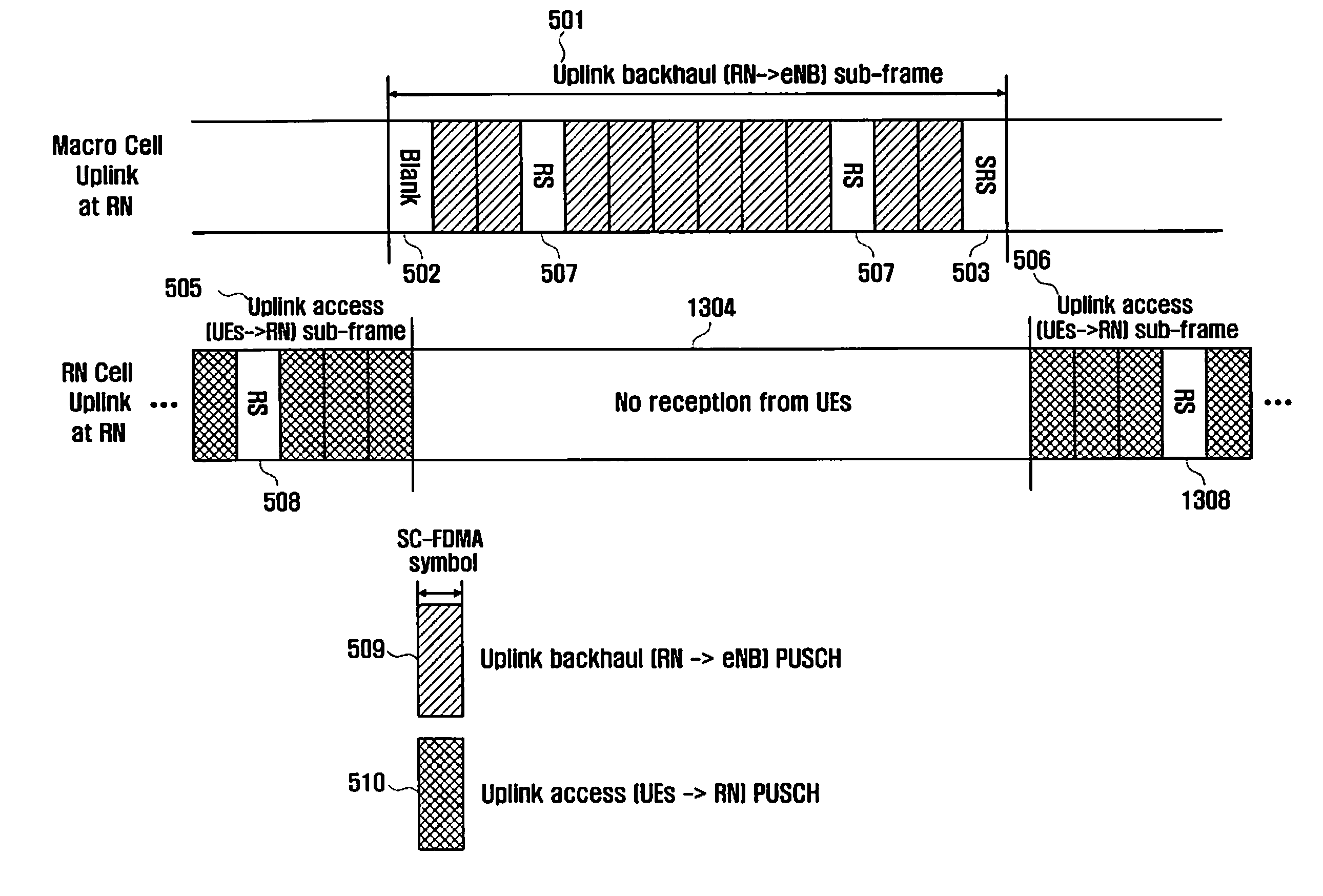
[0058]FIG. 5 is a diagram illustrating an uplink backhaul sub-frame structure in an L3 relay system in accordance with the first embodiment of the present invention. Particularly, the first embodiment takes into consideration the case of allowing SRS transmission in an uplink backhaul sub-frame. The SRS is used for the regulation of transmission timing of a relay node. Also, channel condition information on frequency domain of a wireless backhaul link obtained through the SRS by a base station is used for scheduling of wireless backhaul resources.

[0059]Referring to FIG. 5, a reference number 501 indicates an uplink backhaul sub-frame region used for transmission from a Relay Node (RN) to a base station which is also referred to as e-Node-B (eNB) in 3GPP terminology. Since the relay node has no reception in the uplink backhaul sub-frame region 501, no uplink resources are allocated to User Equipment (UE) in a relay node cell as indicated by a reference number 504....

second embodiment

The Second Embodiment

[0072]FIG. 8 is a diagram illustrating an uplink backhaul sub-frame structure in an L3 relay system in accordance with the second embodiment of the present invention. Particularly, the second embodiment is limited to the case where an uplink backhaul sub-frame does not transmit the SRS.

[0073]Referring to FIG. 8, a reference number 801 indicates an uplink backhaul sub-frame region used for transmission from the Relay Node (RN) to the base station (e.g. eNB). Since the relay node has no reception in the uplink backhaul sub-frame region 801, no uplink resources are allocated to User Equipment (UE) in a relay node cell as indicated by a reference number 803. Regions except the uplink backhaul sub-frame region 801 correspond to uplink access sub-frame regions 804 and 805 of user equipment in the relay node cell. The relay node receives signals from user equipment in these regions 804 and 805.

[0074]Since the sync of the uplink backhaul sub-frame of the relay node coin...

third embodiment

The Third Embodiment

[0078]FIG. 9 is a diagram illustrating a downlink backhaul sub-frame structure in an L3 relay system in accordance with the third embodiment of the present invention.

[0079]Referring to FIG. 9, the Relay Node (RN) sends PDCCH 912 to User Equipment (UE) in the relay node cell just before receiving a downlink backhaul sub-frame from the base station (e.g. eNB). Also, the base station may transmit the downlink backhaul sub-frame by performing a Frequency Division Multiplexing (FDM) for PDCCH 902 and PDSCH 903 of user equipment in the macro cell. This structure is for the purpose of maintaining the compatibility with conventional LTE systems.

[0080]In the third embodiment as well, RF transmission / reception switching time delays 906 and 907 are invoked respectively just before and just after reception of the downlink backhaul sub-frame. In order to apply such a switching time delay to the backhaul sub-frame, the base station does not use the last OFDM symbol in transmis...


PUM


Abstract

In a relay based wireless communication system, a method for transmitting an uplink backhaul of a relay node includes obtaining scheduling information for an uplink backhaul sub-frame through a downlink backhaul control channel from a base station, and performing a rate matching and mapping of data by regarding at least one predefined symbol as a blank symbol. The predefined symbol is located at a front part or a rear part of the scheduled uplink backhaul sub-frame. The transmitting method further includes performing a multiplexing of the uplink backhaul sub-frame, and transmitting the multiplexed uplink backhaul sub-frame. This method can eliminate an overlap of transmission and reception timing in a relay node due to an RF transmission / reception switching time delay. Also, the method can make better use of wireless backhaul resources and minimize an influence on conventional systems by offering the compatibility with conventional uplink and downlink sub-frame structures.

Description

PRIORITY[0001]This application claims priority to applications filed with the Korean Intellectual Property Office on Mar. 11, 2009 and Jun. 22, 2009 and assigned Serial Nos. 10-2009-0020660 and 10-2009-0055597, respectively, the content of which are incorporated herein by reference.BACKGROUND OF THE INVENTION[0002]1. Field of the Invention[0003]The present invention relates in general to a wireless relay of a wireless communication system and, more particularly, to a method and apparatus for designing backhaul sub-frames of an uplink and a downlink for a layer-3 relay including the functions of a base station.[0004]2. Description of the Related Art[0005]In modern mobile communication systems, Orthogonal Frequency Division Multiplexing (OFDM) and Single Carrier Frequency Division Multiple Access (SC-FDMA) have been widely studied as useful techniques for high-rate data transmission in a wireless channel. OFDM and SC-FDMA techniques are employed respectively for the downlink and uplin...

Claims


Application Information

Patent Timeline
Patent Type & Authority Applications(United States)
IPC IPC(8): H04W72/04H04B7/14H04J11/00
CPCH04L1/00H04B7/15507H04B7/2606H04L2001/0097
Inventor LEE, IN HOCHO, JOON YOUNGHAN, JIN KYULEE, JU HO
Owner SAMSUNG ELECTRONICS CO LTD
Why Eureka
Try Eureka