Cartridge For A Fluid Sample Analyser

Inactive Publication Date: 2010-09-16
INVERNESS SWITZERLAND GMBH
View PDF4 Cites 2 Cited by
  • Summary
  • Abstract
  • Description
  • Claims
  • Application Information

AI Technical Summary

Benefits of technology

[0040]The insert may to advantage be of a cruciform shape.
[0041]Such a shape enables fluid inlets/outlets to be accommodated, along with fixing points for attachments to said other housing part, in a relatively small area Consequently, the cartridge can ha

Problems solved by technology

Similarly, there will be a small amount of misalignment between the parts of the docking mechanism that locate the top and bottom halves of the cartridge.
In addition, rel

Method used


Image

  • Cartridge For A Fluid Sample Analyser
  • Cartridge For A Fluid Sample Analyser
  • Cartridge For A Fluid Sample Analyser

Examples


first embodiment

[0058]Since the first embodiment is similar in many respects to the cartridge shown in PCT / GB2006 / 001162, the latter will first be described.

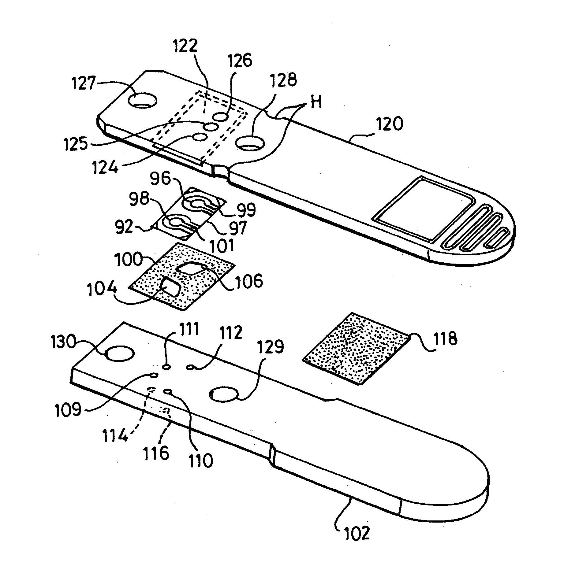
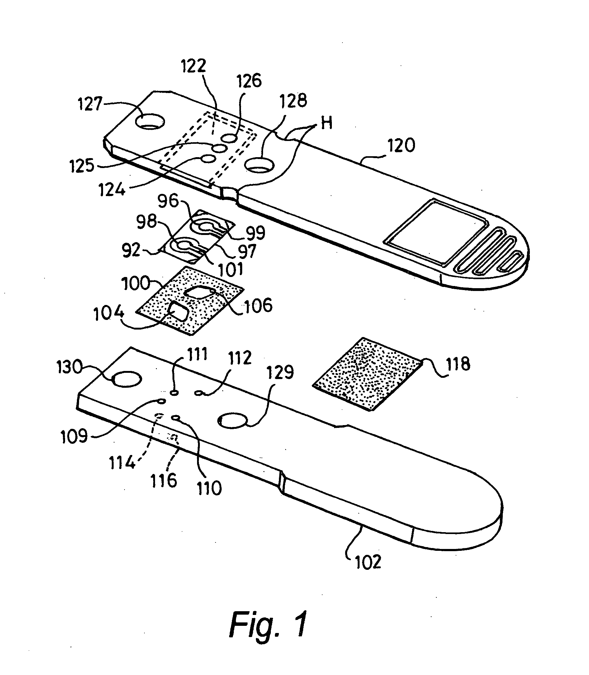
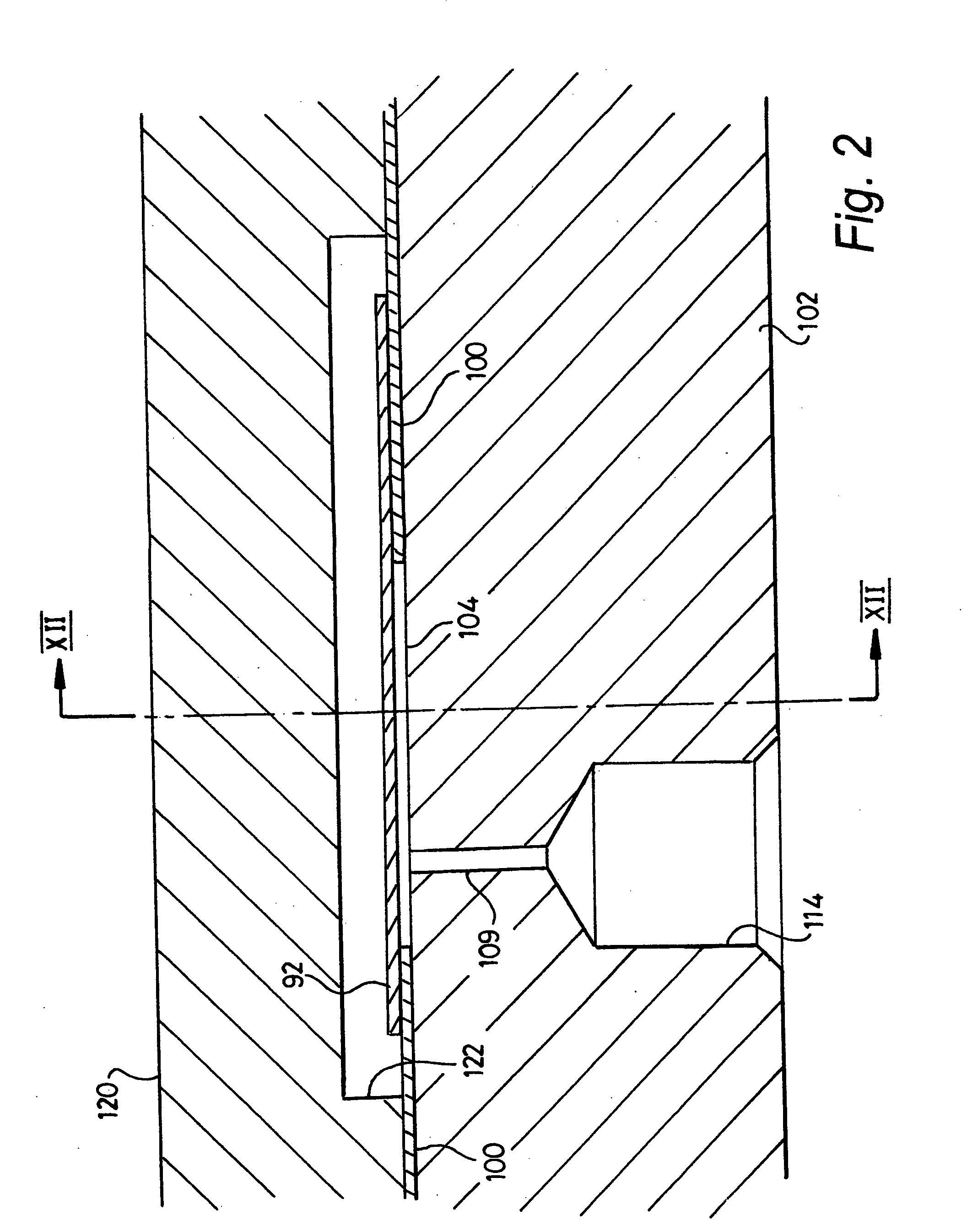
[0059]With reference to FIG. 1, the quartz crystal plate is denoted by reference numeral 92, and forms part of the cartridge shown in the drawings. The plate is coated on one surface with gold in a pattern that defines a pair of drive electrodes 96 and 98, each of which is in registry with a respective one of two separate flow cells. The underside of the plate is also coated with gold to form a common earth electrode. A conductive track (not shown) runs from this electrode around the edge of the plate to the top surface of the plate to provide a contact for enabling a coda pin engaging the top surface of the plate to connect to the earth electrode.

[0060]The transducer 92 is adhered to the top surface of an adhesive membrane 100 the underside of which is adhered to a plate 102. The upper surface of plate 102 constitutes a support surface for the...

third embodiment

[0112]The cartridge shown in FIG. 14 has many features which are very similar to those of cartridge, and these features are therefore denoted by the reference numerals used in FIGS. 6 and 7, raised by 100.

[0113]In this particular case, the insert 302 is rectangular, and the spacing and geometry of the fingers 321-324 are such as to enable the insert 302 to be accommodated in the housing part 300.


PUM


Abstract

A cartridge is used in apparatus for analysing a sample comprising a fluid and has a sample receiving cell which receives the fluid for analysis. The cell comprises a surface on one of two housing parts (120; 200; 300; 102; 202; 302) and a sensor comprising an electrical-mechanical transducer (92; 240; 340) spaced from said surface. The sensor is attached to one of the housing parts by an adhesive membrane (100; 246; 346) wherein the membrane is attached only to one of said parts of housing so that any slight relative movement or flexing of the housing parts does not result in forces being applied to the sensor via the membrane.

Description

FIELD OF THE INVENTION[0001]This invention relates to a cartridge for apparatus for analysing a sample comprising a fluid, and in particular to a cartridge having a sensor, for performing that analysis, comprising an electrical-mechanical transducer.BACKGROUND TO THE INVENTION[0002]The invention is applicable to apparatus in which a transducer modifies an applied electrical signal, in particular to apparatus, for example a quartz crystal microbalance system, having a piezoelectric transducer which vibrates at a frequency at or close to its resonant frequency.[0003]The transducer typically has an active surface on which a receptor group is immobilised. That group has a chemical affinity or reactivity towards the substance to be detected or analysed. The substance to be analysed is normally present in a fluid which is brought into contact with the active surface of crystal.[0004]Physical, chemical and biochemical interactions between the receptor group on the surface and the substance...

Claims


Application Information

Patent Timeline
IPC IPC(8): G01N27/00
CPCG01N2291/0257G01N29/036
Inventor FROGLEY, MARK JOHNHAMMOND, CHRISTOPHER JOHNMOORE, STUARTWHIELER, KLAUS
Owner INVERNESS SWITZERLAND GMBH
Why Eureka
Try Eureka