Solid-state battery and method for manufacturing of such a solid-state battery

a solid-state battery and manufacturing method technology, applied in sustainable manufacturing/processing, secondary cell servicing/maintenance, non-aqueous electrolyte cells, etc., can solve the problems of shortening battery life, difficult to deposit pinhole-free on the surface of the battery, shortening the battery, etc., to increase the rate capability of the battery and increase the performance of the battery

Inactive Publication Date: 2010-09-16
KONINKLIJKE PHILIPS ELECTRONICS NV
View PDF9 Cites 40 Cited by
  • Summary
  • Abstract
  • Description
  • Claims
  • Application Information

AI Technical Summary

Benefits of technology

[0005]The layer thickness of the solid-state electrolytic layer is preferably less than 500 nm, preferably 100 nm, more preferably less than 60 nm, and most preferably substantially 50 nm. In this manner a relatively thin electrolytic layer is applied, leading—compared to known (relatively thick) electrolytic layers—to a considerable decrease of the impedance of the electrolytic layer, resulting in a considerably improved battery performance.
[0012]In a particular preferred embodiment a surface of at least one electrode facing the electrolyte is patterned at least partially. In this manner the effective contact surface area between the electrode(s) and the electrolyte is increased substantially with respect to a conventional relatively smooth contact surface of the electrode(s), resulting in a proportional increase of the rate capability of the battery obtained by the method according to the invention. Patterning the surface of one or multiple electrodes facing the electrolyte can be realised by means of various methods, among others selective wet chemical etching, physical etching (Reactive Ion Etching), mechanical imprinting, and chemical mechanical polishing (CMP). The pattern of the electrode(s), increasing the contact surface area between the electrode(s) and the electrolyte, can be shaped in various ways. Preferably, the patterned surface of at least one electrode is provided with multiple cavities, in particular pillars, trenches, slits, or holes, which particular cavities can be applied in a relatively accurate manner. In this manner the increased performance of the battery can also be predetermined in a relatively accurate manner.

Problems solved by technology

It has been found, however, that it is very difficult to deposit pinhole-free UPON layers with a thickness below 1 micron, wherein it is noted that already a single pinhole in the solid-state electrolyte can result in shorted electrodes, and hence in a shorted battery.

Method used


Image

  • Solid-state battery and method for manufacturing of such a solid-state battery
  • Solid-state battery and method for manufacturing of such a solid-state battery
  • Solid-state battery and method for manufacturing of such a solid-state battery

Examples


Embodiment Construction

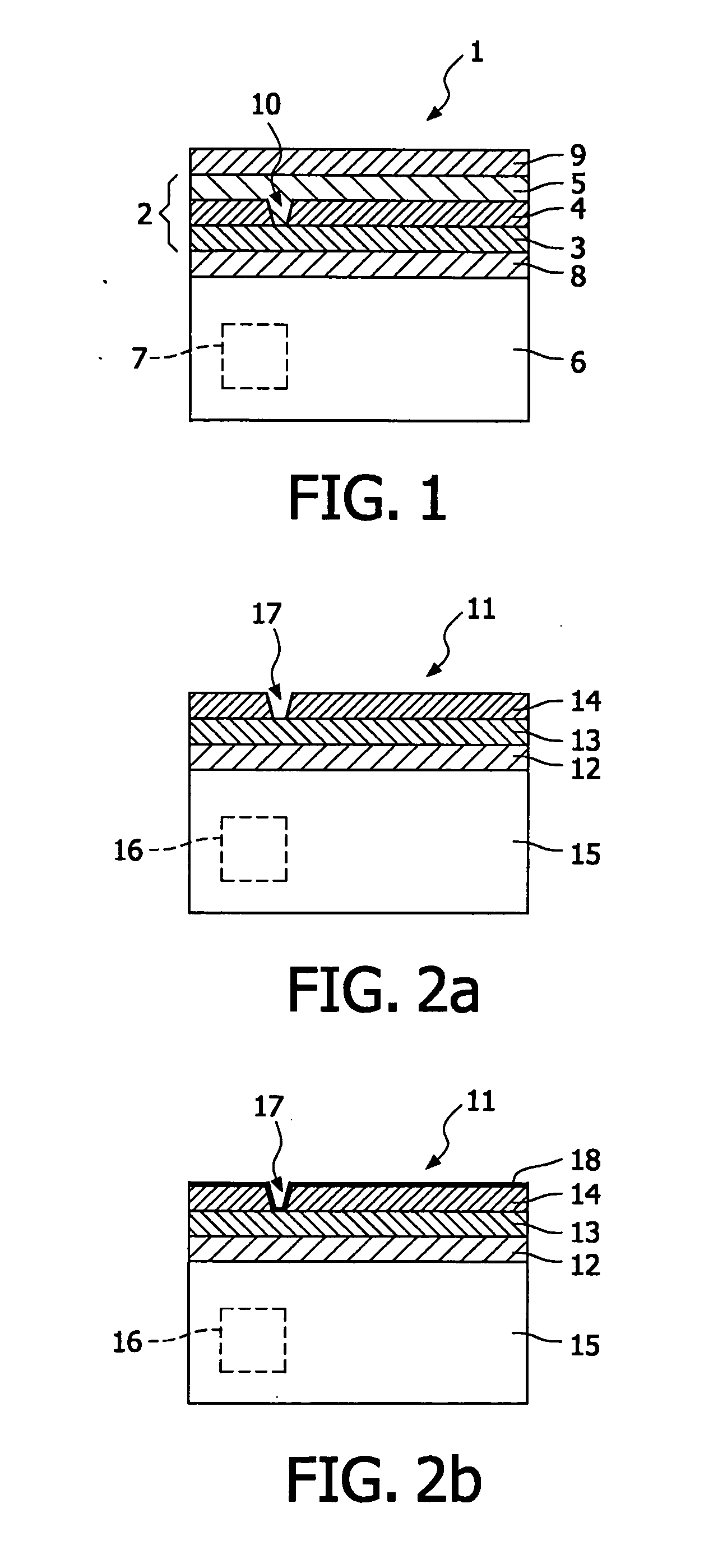
[0018]FIG. 1 shows a schematic cross section of a battery 1 known from the prior art. An example of the battery 1 shown in FIG. 1 is also disclosed in the international patent application WO2005 / 027245. The known battery 1 comprises a lithium ion cell stack 2 of an anode 3, a solid-state electrolyte 4, and a cathode 5, which cell stack 2 is deposited onto a substrate 6 in which one or more electronic components 7 are embedded. In this example the substrate 6 is made of intrinsic silicon, while the anode 3 is made of amorphous silicon (a-Si). The cathode 5 is made of V2O5, and the solid-state electrolyte 4 is made of LiPON. Between the battery stack 2 and the substrate 6 a lithium barrier layer 8 is deposited onto the substrate 6. In this example, the lithium diffusion barrier layer 8 is made of tantalum. The conductive tantalum layer 8 acts as a chemical barrier, since this layer counteracts diffusion of lithium ions (or other active species) initially contained by the stack 2 into ...


PUM

PropertyMeasurementUnit
thicknessaaaaaaaaaa
thicknessaaaaaaaaaa
thicknessaaaaaaaaaa

Abstract

Batteries based on solid-state electrolytes are known in the art. These (planar) energy sources, or solid-state batteries, efficiently convert chemical energy into electrical energy and can be used as the power sources for portable electronics. The invention relates to a method for manufacturing of a solid-state battery in which the pinholes in a solid electrolyte are at least partially filled by the deposition of an electrically insulating layers. The invention also relates to a battery obtained by performing such a method. The invention further relates to an electronic device provided with such a battery.

Description

FIELD OF THE INVENTION[0001]The invention relates to a method for manufacturing of a solid-state battery. The invention also relates to a battery obtained by performing such a method. The invention further relates to an electronic device provided with such a battery.BACKGROUND OF THE INVENTION[0002]Batteries based on solid-state electrolytes are known in the art. These (planar) energy sources, or ‘solid-state batteries’, efficiently convert chemical energy into electrical energy and can be used as the power sources for portable electronics. At small scale such batteries can be used to supply electrical energy to e.g. microelectronic modules, more particular to integrated circuits (IC's). An example hereof is disclosed in the international patent application WO2005 / 027245, where a solid-state thin-film battery, in particular a lithium ion battery, comprises a structured silicon substrate onto which a stack of a silicon anode, a solid-state electrolyte, and a cathode are deposited suc...

Claims


Application Information

Patent Timeline
Patent Type & Authority Applications(United States)
IPC IPC(8): H01M10/36H01M10/04H01M4/02H01M4/13H01M10/0525H01M10/054H01M10/0562H01M10/0585
CPCH01M4/049Y10T29/49115H01M6/40H01M10/0525H01M10/054H01M10/0562H01M10/0585H01M10/347H01M10/425H01M2300/0068H01M2300/0071H01M2300/0088H01M2300/0094Y02E60/122Y02E60/124H01M4/13Y02E60/10Y02P70/50
Inventor PIJNENBURG, REMCO HENRICUS WILHELMUSNOTTEN, PETRUS HENRICUS LAURENTIUSNIESSEN, ROGIER ADRIANUS HENRICA
Owner KONINKLIJKE PHILIPS ELECTRONICS NV
Why Eureka
Try Eureka