Multi-mode radio transmitters and a method of their operation

a radio transmitter and multi-mode technology, applied in the direction of antennas, amplifiers, electrically long antennas, etc., can solve the problems of difficult to achieve attractive power efficiency, limited efficiency control, and inability to change the average rf output power, etc., to achieve the effect of improving the power efficiency of radio transmitters

Inactive Publication Date: 2010-09-16
NXP BV
View PDF3 Cites 73 Cited by
  • Summary
  • Abstract
  • Description
  • Claims
  • Application Information

AI Technical Summary

Benefits of technology

[0020]It is an object of the present invention to improve the power efficiency of radio

Problems solved by technology

Standard architectures for the transmitter of handsets targeted at these applications necessarily operate the PA linearly, and this makes it difficult to achieve a power efficiency that looks attractive.
Since the rate at which the average RF output power can be changed is usually limited, efficiency control can almost always be applied.
However, as the degree to which the supply track is made to follow the envelope of the modulation is a matter of choice in the case of envelope tracking, the approach is feasible for most of the current cellular radio standards and only becomes impracticable for standards that use an extremely wide bandwidth.
This achieves the highest power efficiency, but puts even greater demands on the transmitter system, as timing issues become more severe, and the PA no longer offers any rejection of noise on its power supply.
Polar modulation is therefore generally more

Method used


Image

  • Multi-mode radio transmitters and a method of their operation
  • Multi-mode radio transmitters and a method of their operation
  • Multi-mode radio transmitters and a method of their operation

Examples


Embodiment Construction

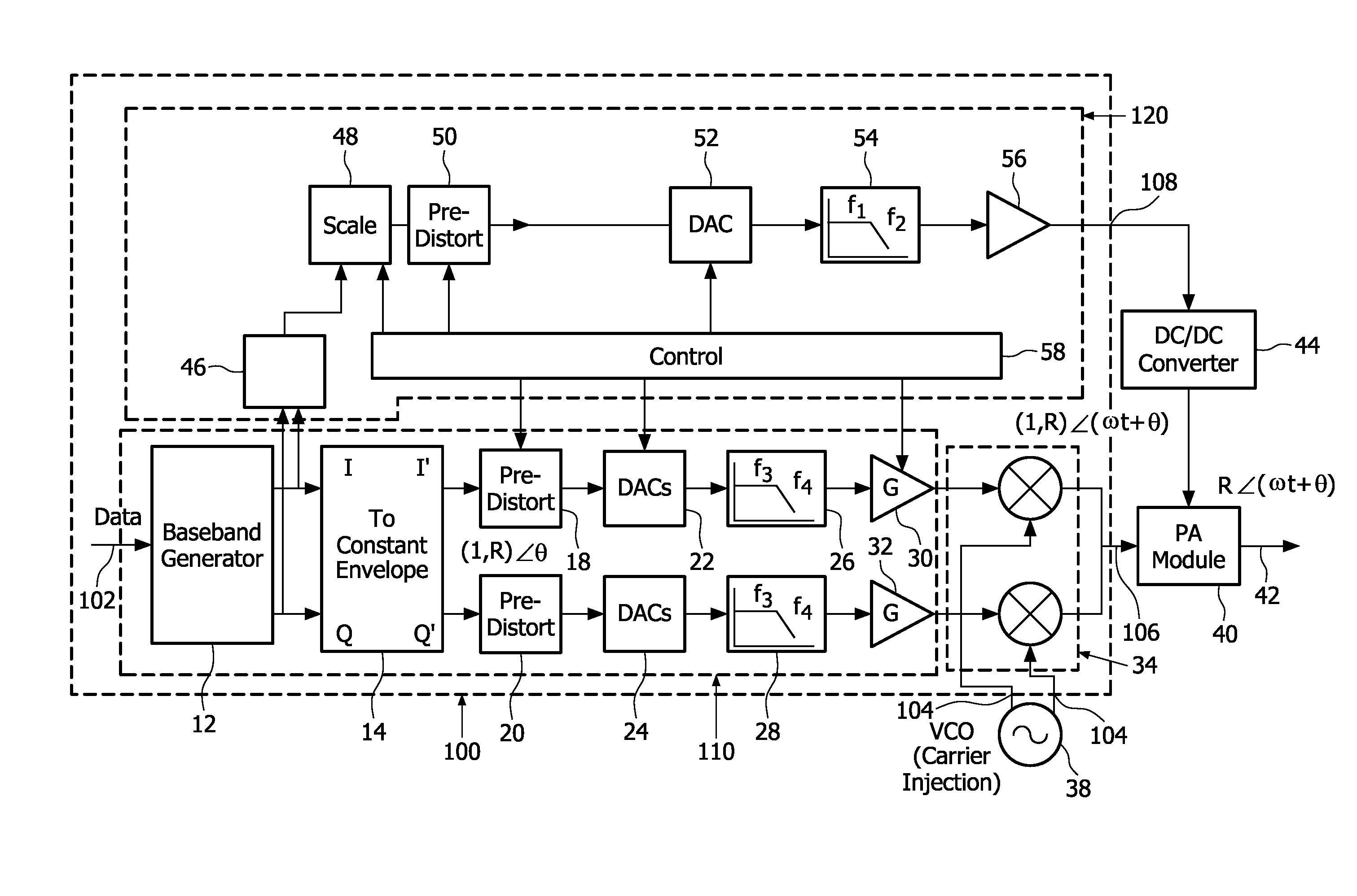
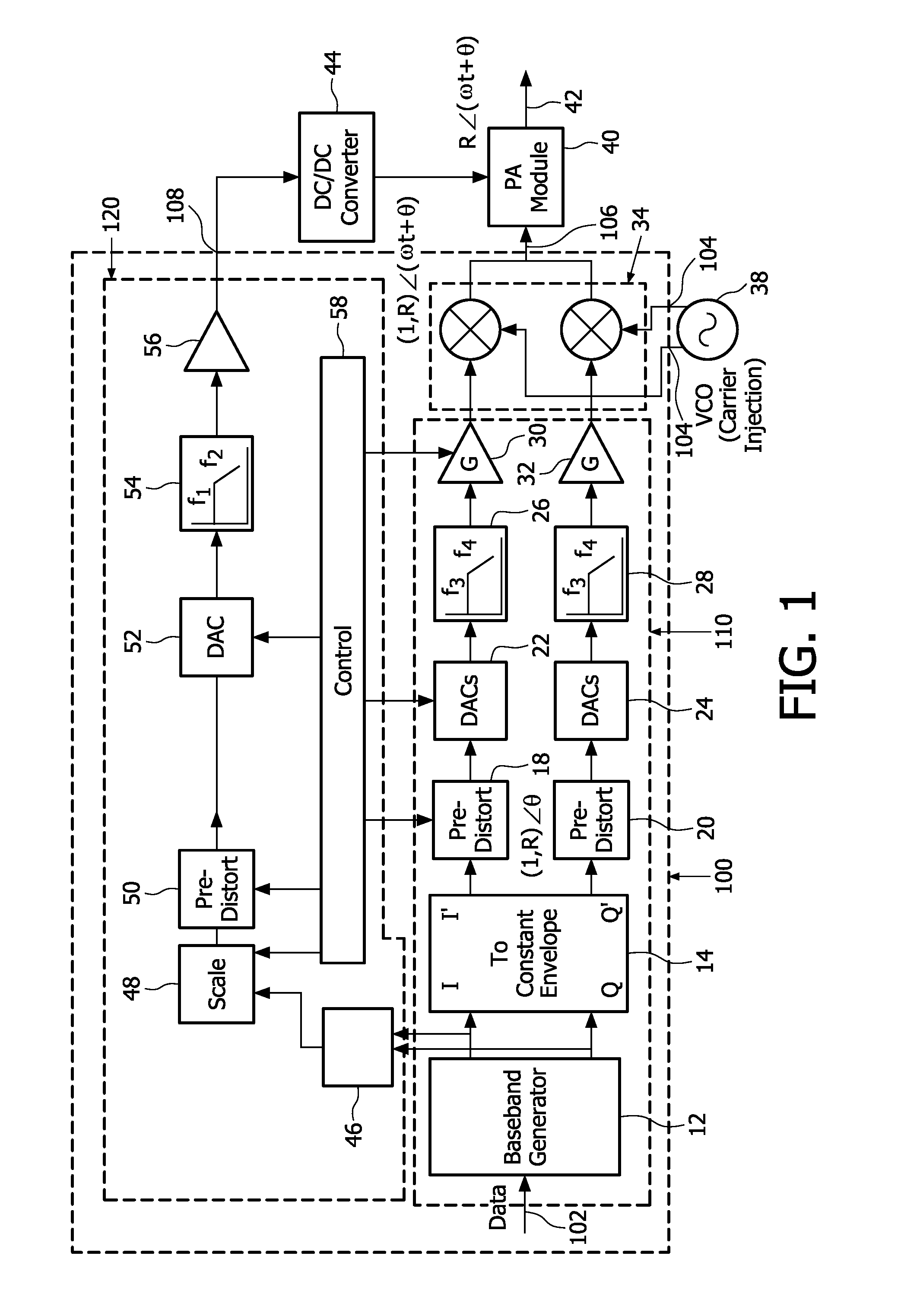
[0036]As FIG. 1 has been described in the preamble of this specification it will not be described again.

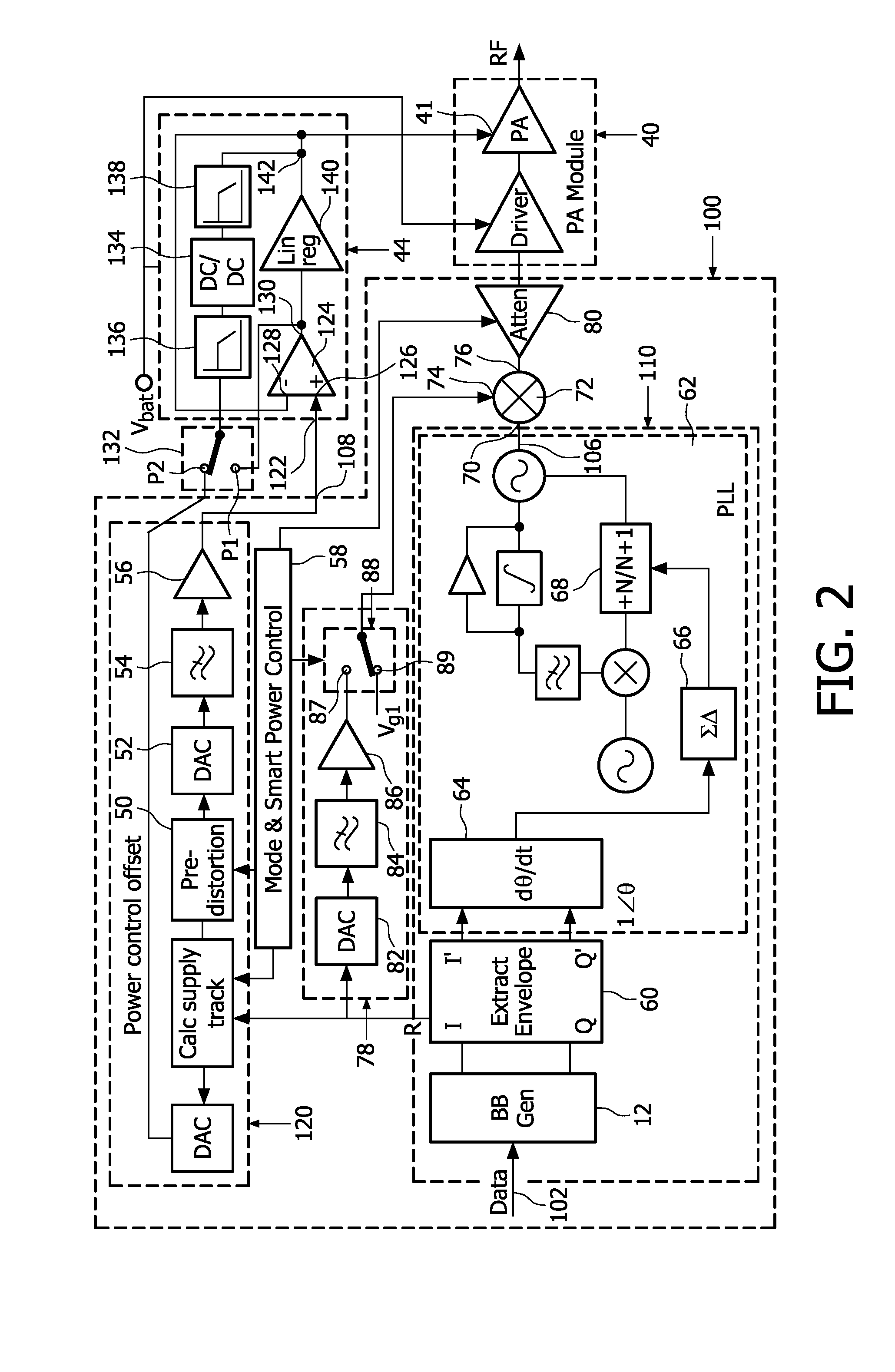
[0037]Referring to FIG. 2, the transmitter shown is a hybrid polar radio transmitter. The transmitter comprises a modulator 100, a power amplifier 40 having a control input 41, and a hybrid supply modulator 44 coupled to the control voltage input 41.

[0038]The modulator comprises a real signal generator 110 having a data input 102 and an output 106 for a real signal at the operating frequency of the transmitter. The data input 102 is coupled to a base band generator 12 which produces quadrature related I and Q signals. The I and Q signals are applied to an envelope extract block 60 which produces a constant envelope output containing just the phase component I′, Q′ of the modulation (for a constant radius) at all RF output power levels. This complex constant envelope output is converted into a real output signal, at the required carrier frequency, using a fractional-N phase locked ...


PUM


Abstract

A multi-mode radio transmitter for use in mobile radio cellular standards, such as 2G, 2.5G and 3G, and a method of operating the transmitter in which an input signal is modulated independently of controlling the drive of a power amplifier (PA) module (40). The transmitter comprises circuitry (12, 60) for extracting the phase (θ) and amplitude (R) components from envelope information in the input signal. A modulator (110) uses the phase component (θ) to produce a constant-envelope signal comprising a phase modulated real signal at the transmitter frequency. This signal is multiplied in a multiplier (72) with either a fixed bias voltage (Vg1) to produce a constant envelope signal or a low level envelope tracking signal derived from an amplitude component (R) by a first amplitude control circuit (78) to produce a signal modulated exactly by the amplitude component. An output from the multiplier is applied to the PA module (40) having a control input (41). The PA module is controllable in a plurality of manners dependent on the characteristics and the required output power of the signal being transmitted. These manners include applying a predetermined fixed voltage to the control input or a less precise envelope tracking signal which is derived by a second amplitude control circuit (120) from the amplitude component (R).

Description

TECHNICAL[0001]The present invention relates to multi-mode radio transmitters and to a method of operating such transmitters. The invention has particular, but not exclusive, application to hybrid polar radio transmitters.BACKGROUND ART[0002]One of the key drivers in determining what constitutes the best architecture for a radio transmitter, especially for battery-powered applications, is the achievement of high power efficiency.[0003]The Global System for Mobile Communications (GSM) is a second-generation (2G) cellular radio standard that uses constant-envelope modulation. It is therefore comparatively easy to achieve a high power efficiency in the transmitter of handsets targeted at this standard, as the power amplifier (PA) can be operated in saturation. Operating the PA in saturation has established a benchmark for power efficiency that the market expects to be maintained in products targeted at more advanced cellular radio standards than GSM.[0004]Third-generation (3G) cellular...

Claims


Application Information

Patent Timeline
IPC IPC(8): H04B1/04
CPCH03F1/0211H04B1/0475H03F3/24
Inventor MINNIS, BRIAN J.MOORE, PAUL A.
Owner NXP BV
Why Eureka
Try Eureka