Work Machine

a work machine and cylinder head technology, applied in the field of work machines, can solve the problems of engine stall risk, reduced rotational speed of the engine, and malfunction of the flushing valve, so as to prevent sudden speed change, improve the response performance of the anti-stall feature, and prevent sudden speed change

Active Publication Date: 2010-09-23
KUBOTA LTD
View PDF6 Cites 19 Cited by
  • Summary
  • Abstract
  • Description
  • Claims
  • Application Information

AI Technical Summary

Benefits of technology

[0047]With this arrangement, when the pressure of the pressure receiving portions to which the other end of the escape oil passageway is communicated is smaller than the primary pressure of the traveling operating apparatus, the check valve is closed, so that the pilot pressure is allowed to communicate via the shock relieving throttle in the hydraulic passageway between the traveling operating apparatus and the pressure receiving portions, thus preventing sudden speed change.
[0048]And, when an excessive load is applied suddenly to the engine, thus resulting in sudden drop in the primary pressure of the traveling operating apparatus and the pressure of the pressure receiving portions to which the other end of the escape oil passageway is communicated is greater than the primary pressure of the traveling operating apparatus, the check valve is opened, so that the pressure of the pressure receiving portion is allowed to escape through the escape oil passageway to the primary side of the traveling operating apparatus, and the swash plate of the HST pump returns to the neutral side speedily.
[0049]Therefore, sudden speed change is prevented by the shock relieving throttle and at the same time, the response performance of the anti-stall feature can be improved by the simple arrangement of providing a check valve in the escape oil passageway.

Problems solved by technology

In the case of a work machine configured such that its traveling apparatus is driven via an HST, if a significant load is applied to the HST motor during traveling, this load will be transmitted to the engine via the HST pump, so the rotational speed of the engine will be reduced, thus presenting the risk of stall of the engine.
However, if the amount of the escape of the oil from the flushing relief valve is increased, due to the corresponding increase of the oil introduced to the flushing valve, e.g. malfunction of this flushing valve may occur.
Further, there is a limit in increasing the amount of escape of the oil from the charge relief valve.
Therefore, there is a limit in improvement of the anti-stall feature with these methods.
Further, in the case of an arrangement wherein the rotational speed of the engine is detected and a controller effects a control so that the control pressure of the swash plate of the HST pump is dropped speedily in response to application of excessive load to the engine, this will result in great complexity of the construction, thus inviting cost increase.

Method used


Image

  • Work Machine
  • Work Machine
  • Work Machine

Examples


first embodiment

[0069]First, with reference to FIGS. 1-9, a first embodiment will be described.

[0070]In FIG. 4 and FIG. 5, a work machine 1 (truck loader) relating to the present invention includes a machine body 2, a work implement 3 mounted on the machine body 2, and a pair of right / left traveling apparatuses 4 supporting the machine body 2, and a cabin 5 (driver protecting apparatus) is mounted at an upper portion on the machine body 2, with an offset to the forward side.

[0071]The machine body 2 is formed of iron plates or the like, and includes a bottom wall 5, a pair of right / left side walls 7, a front wall 8 and support frames 9 provided at the rear portions of the right / left respective side walls 7. Between the side walls 7, there is formed an upwardly opened space, and at the rear end of this machine body 2, there is provided an openable / closable lid member 10 for closing the rear end opening between the right / left support frames 9.

[0072]The cabin 5 is mounted with its front lower end in co...

second embodiment

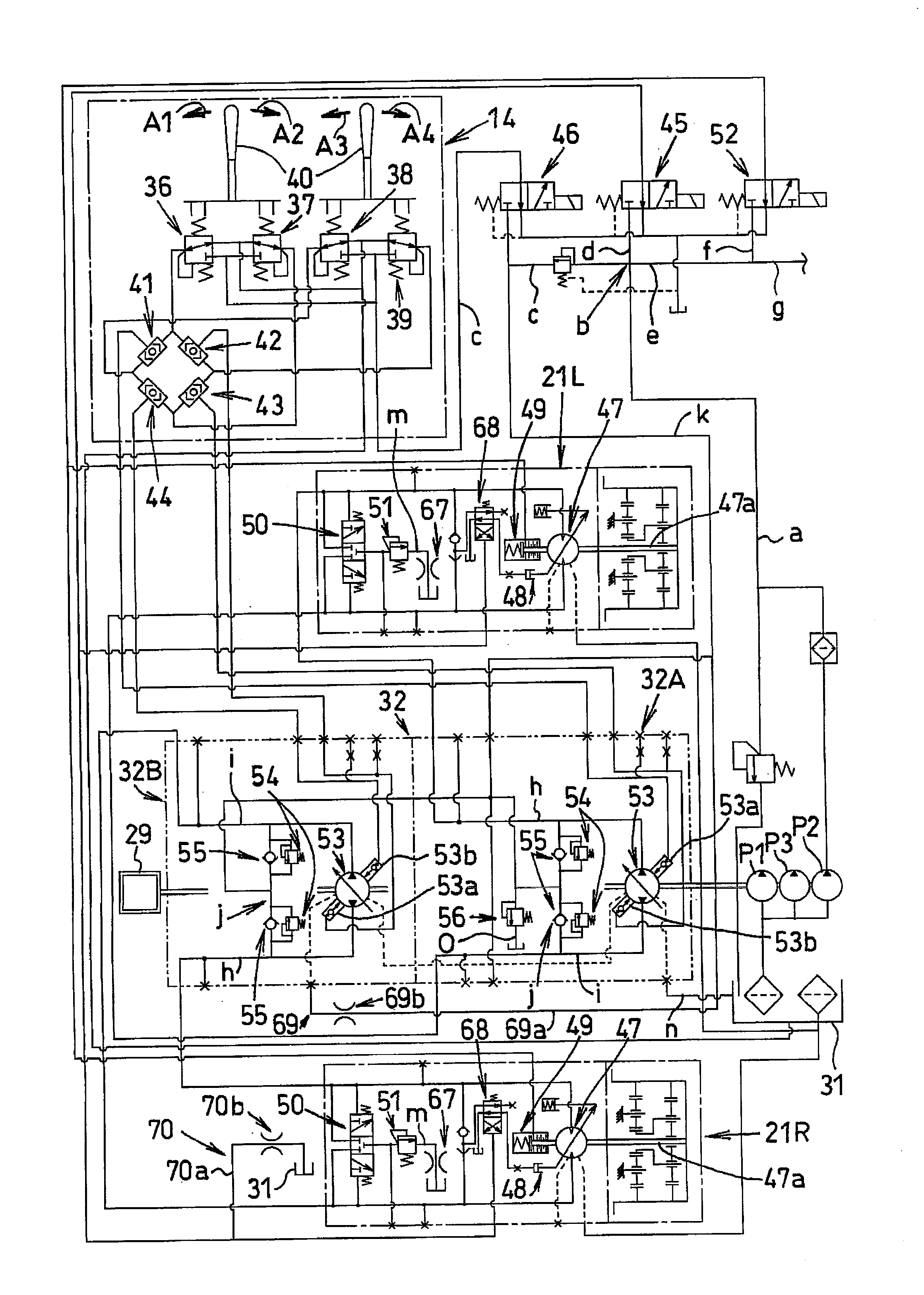
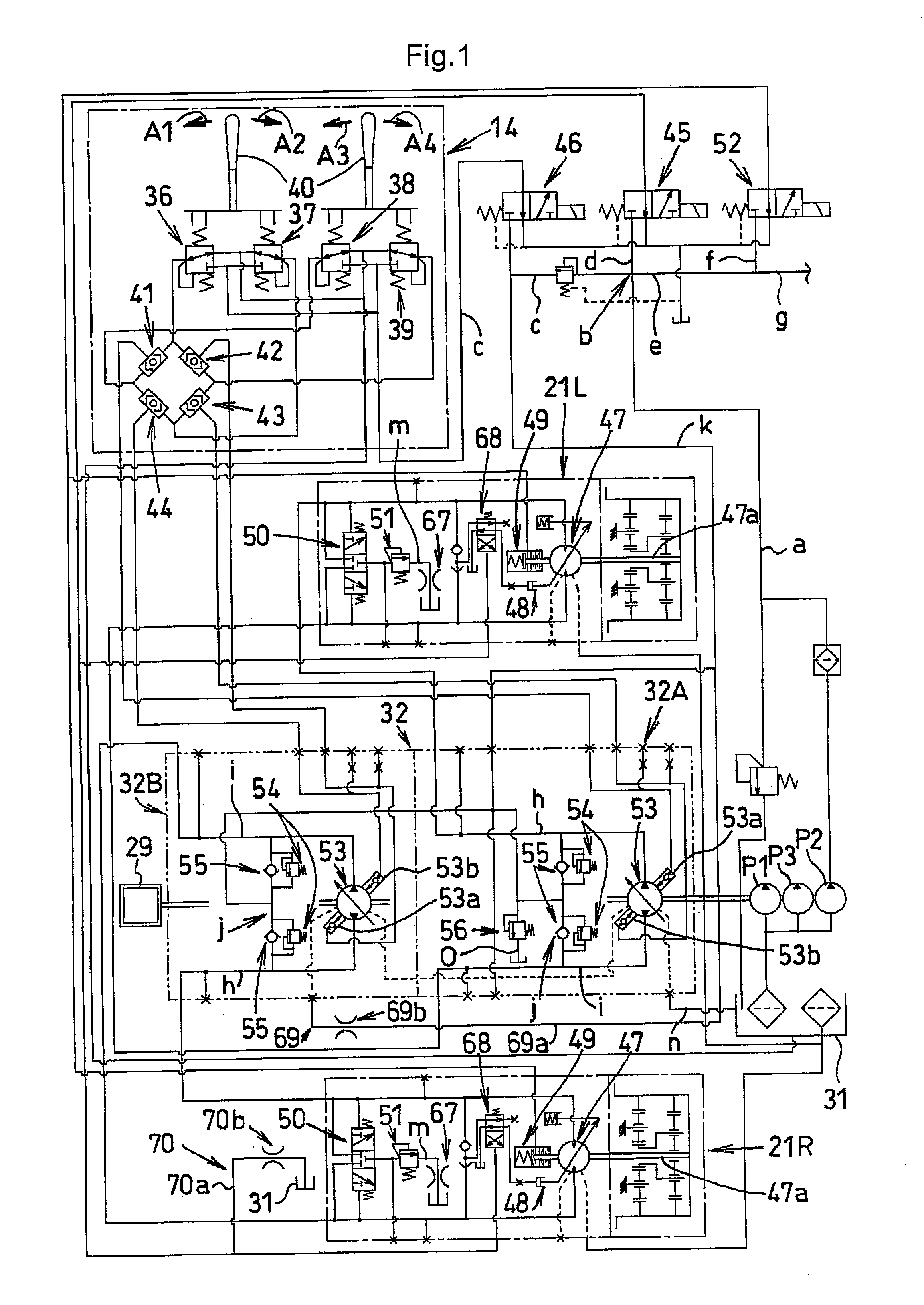
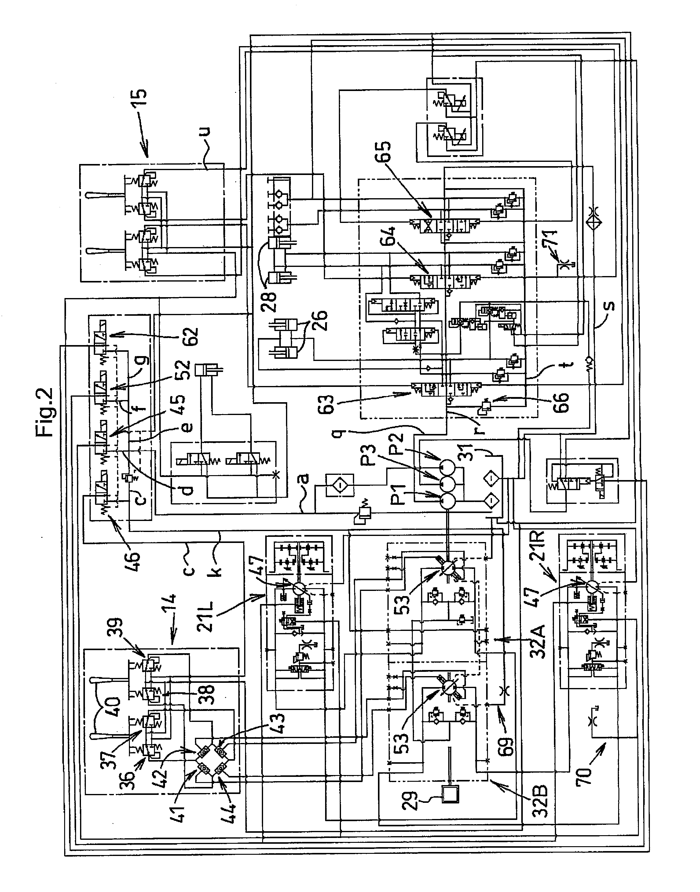
[0159]Next, with reference to FIGS. 10-15, a second embodiment will be described. The hydraulic system relating to this embodiment is also applicable to a truck loader (work machine) 1 shown in FIGS. 4-5.

[0160]In the hydraulic system of the work machine 1 shown in FIGS. 10-14, the first through third pumps P1, P2, P3 each is comprised of a fixed displacement type gear pump driven by the power of the engine 29.

[0161]The first pump P1 (main pump) is used for driving a hydraulic actuator of an attachment attached to the leading end of the lift cylinder 26, the bucket cylinder 28 or the arm 22.

[0162]The second pump P2 (pilot pump or charge pump) is used mainly for supplying a control signal pressure (pilot pressure).

[0163]The third pump P3 (sub pump) is used for increasing a flow rate of work oil supplied to a hydraulic actuator of a hydraulically driven attachment attached to the leading end of the arm 22 in case this hydraulic actuator requires a large capacity.

[0164]The traveling ope...


PUM


Abstract

Disclosed is a work machine having a traveling apparatus and a work implement driven by an engine. A hydraulic system mounted on the work machine includes an HST pump comprising a swash plate, variable displacement pump driven by the engine, an HST motor connected in a closed circuit to the HST pump and a pair of speed-changing oil passageways, the HST motor being driven by an amount of oil supplied by the HST pump, thereby to drive the traveling apparatus, a main pump driven by the engine, the main pump supplying pressure oil to the work implement, a pilot pump driven by the engine, a swash plate positioning circuit configured to effect positioning of a swash plate of the HST pump with pilot oil supplied from the pilot pump, and a bleed circuit configured to drain, via a throttle, a portion of the pilot oil supplied to the swash plate positioning circuit.

Description

BACKGROUND OF THE INVENTION[0001]1. Field of the Invention[0002]The present invention relates to a work machine such as a truck loader, a skid loader, etc. in which a traveling apparatus is driven via an HST (hydrostatic transmission) configured to drive an HST motor by an HST pump comprising a swash plate, variable displacement pump driven by an engine.[0003]2. Description of the Related Art[0004]As an example of a work machine including a traveling apparatus driven via an HST, there is known a machine including an HST pump comprising a swash plate, variable displacement pump, an HST motor connected in a closed circuit to this HST pump and a pair of speed-changing oil passageways and configured to be driven by discharge oil from the HST pump to drive a traveling apparatus, a charge circuit for supplementing an amount of oil from a charge pump to the speed-changing oil passageways, a charge relief valve for determining the circuit pressure of the charge circuit, a flushing valve for...

Claims


Application Information

Patent Timeline
Patent Type & Authority Applications(United States)
IPC IPC(8): F16D31/02
CPCE02F9/2232E02F9/2235E02F9/2253F15B2211/20561F16H61/433F15B2211/3116F15B2211/6355F15B2211/7058F16H61/4104F15B2211/20576
Inventor SUMIYOSHI, RYOHEIARII, KAZUYOSHISUZUKI, KUNIHIRO
Owner KUBOTA LTD
Why Eureka
Try Eureka