Brushless counter-rotating electric apparatus and system

a technology of electric apparatus and electric wheel hub, which is applied in the direction of propulsive elements, marine propulsion, vessel construction, etc., can solve the problems of high manufacturing cost, difficult fabrication, and limited operation life of such motors, and achieve the effect of improving the efficiency of brushless counter-rotating electric wheel hub

Inactive Publication Date: 2010-09-23
E WISH TECH
View PDF40 Cites 50 Cited by
  • Summary
  • Abstract
  • Description
  • Claims
  • Application Information

AI Technical Summary

Benefits of technology

[0020]A third object of the subject invention is to improve the efficiency of a brushless counter-rotating electric motor by accessing torsional forces normally lost to stationary motor mounts that hold the stator or armature in a fixed position.
[0021]Another objective of the subject invention is to improve the efficiency of a brushless counter-rotating DC / AC electric apparatus by accessing torsional forces normally lost to stationary anchoring mounts by allowing the stator and armature to rotate freely, wherein the armature and attached armature output means rotates in one direction and the stator rotates in an opposite direction about a common central axis and necessary electrical contact is maintained via at least one electrically conductive grease-containing bearing assembly or equivalent non-brush electrical contact assembly.
[0022]Yet a further objective of the subject invention is to improve the efficiency of a brushless counter-rotating electric wheel hub motor for use with a wheeled vehicle by limiting creation of heat and accessing torsional forces normally lost to stationary motor mounts by rotationally securing a wheel and tire to a rotating stator / outer rotational member and a central axle to a rotating armature / inner rotational member and allowing the mated stator to armature assembly to rotate freely with the armature-connected-axle rotating in one direction and a stator-connected-wheel rotating in an opposite direction and then linking the armature-connected-axle rotation to either the same wheel or at least one other wheel on the vehicle so that both wheels rotate in a common direction.

Problems solved by technology

Clearly, the operational lifetime of such a motor is extremely limited, given its destruction upon hitting a target.
This radial commutator / brush design is complex, not easily fabricated, and, thus, expensive to manufacture.
When counter-rotation of motor components is part of the operation of the device the means for electrical communication is critically important and extremely difficult to achieve.
Unfortunately, the manner in which the device receives or delivers electricity is not related, nor are any internal electrical components described.

Method used


Image

  • Brushless counter-rotating electric apparatus and system
  • Brushless counter-rotating electric apparatus and system
  • Brushless counter-rotating electric apparatus and system

Examples


fifth embodiment

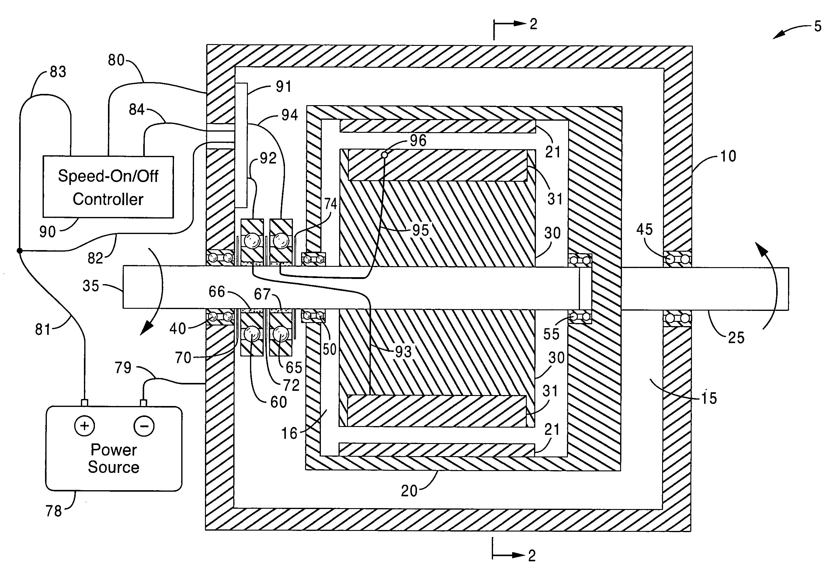
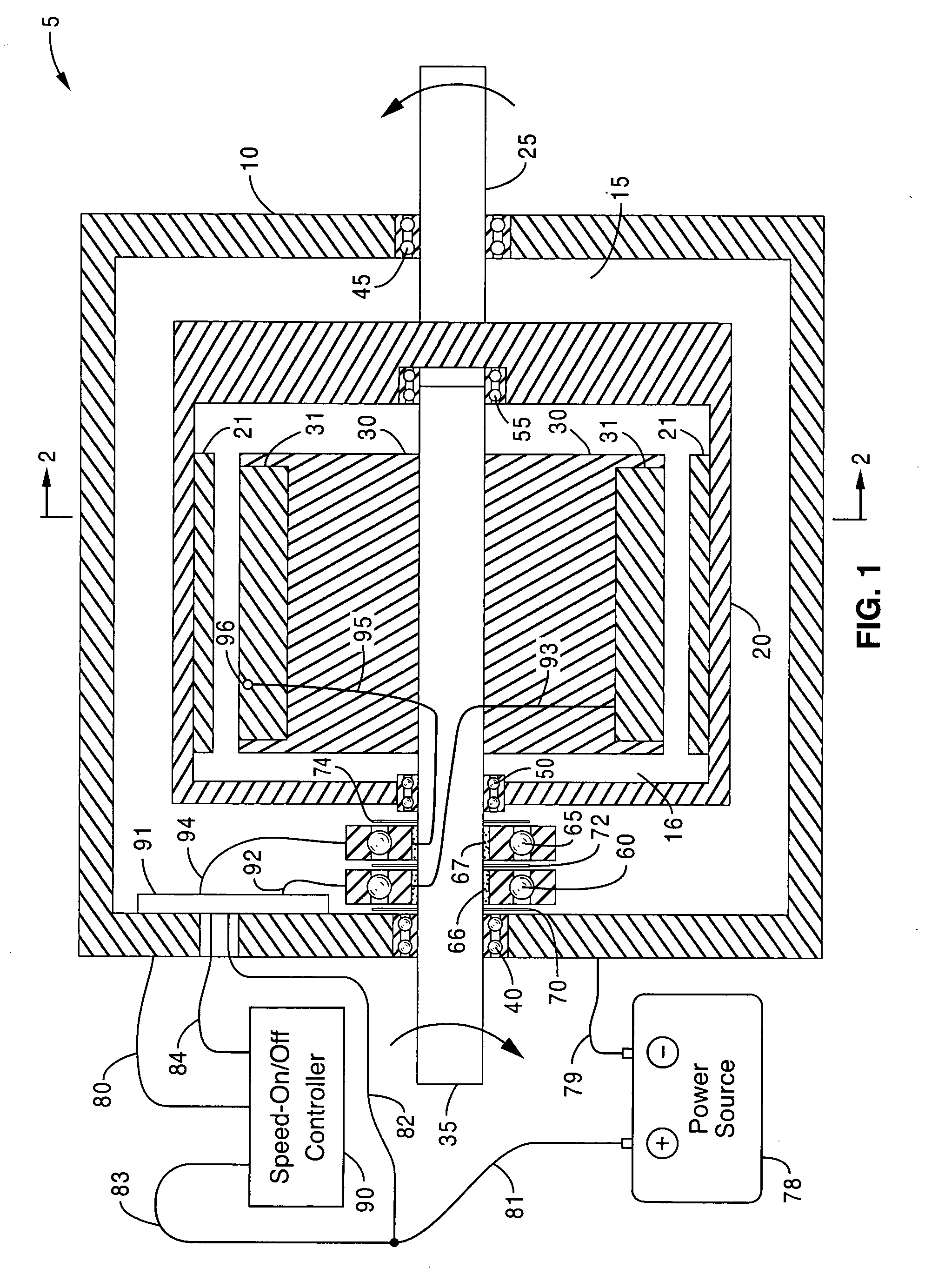
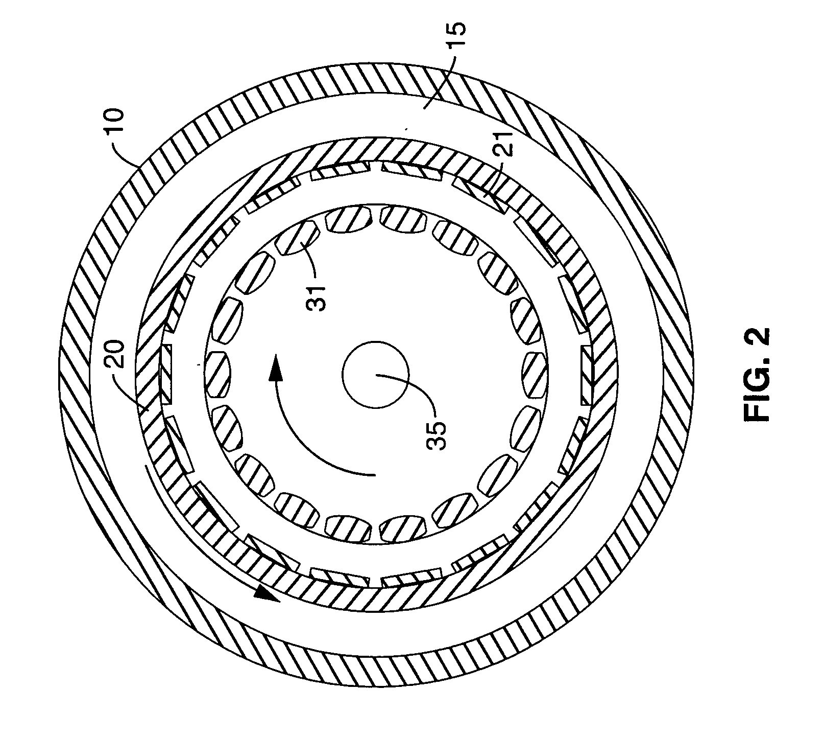
[0097]FIG. 17 shows the subject invention in which a rotational-reversal set of gears is included. The result is that, like the embodiments shown in FIGS. 7-16 the opposite rotational outputs of the stator and armature are mated back into the same wheel. The subject brushless counter-rotating wheel hub motor 505 includes a stator or outer rotational member 520. Secured to the inner lining of the stator 520 are permanent magnets 521. It is stressed that in this exemplary device the permanent magnets are associated with the stator or outer rotational member and the windings are on the armature or inner rotational member, but the permanent magnets may be positioned on the armature and the windings on the stator or electromagnets may substitute for the permanent magnets in either location.

[0098]Mounted within the stator 520 is an armature or inner rotational member 530 that is attached to a hollow armature axle or armature drive shaft 535. Located proximate the outer perimeter of the ar...

sixth embodiment

[0110]Attached to the hollow armature axle 635 is a sprocket 643 upon which a chain is attached that carries the armature 630 rotational force to the other wheel (it is emphasized that the “fewer bearings” sixth embodiment may be utilized with the other embodiments (armature rotation-reversal methods) herein disclosed in which the armature rotation is reversed and coupled back into the same wheel that contains the subject motor). It is stressed that a sprocket 643 is utilized in this exemplary description; however, equivalent means to a sprocket-and-chain mechanism for transmitting armature motion to the other wheel are contemplated to be within the realm of this disclosure, including belts, cables, gears, and the like and may incorporated energy storing devices (resilient means, springs, and the like) to delay transmission of the rotational force to the other wheel.

[0111]Once again, since both the armature 630 and stator 620 are rotating in opposite directions when the subject brus...


PUM


Abstract

A brushless counter-rotating electric apparatus, motor, wheel hub motor, and associated vehicle includes a brushless counter-rotating electric motor that has oppositely rotating armature and stator components, oppositely rotating armature and stator output drives and, when associated with a vehicle, a control assembly for speed-on / off control of the motor and a portable electric power supply.

Description

CROSS-REFERENCE TO RELATED APPLICATIONS[0001]This application is a continuation-in-part of copending application Ser. No. 12 / 584,557 filed on Sep. 8, 2009, which is a continuation-in-part of copending application Ser. No. 12 / 387,413 filed on May 1, 2009 which claims priority from U.S. provisional applications Ser. No. 61 / 126,320 filed on May 2, 2008 and Ser. No. 61 / 137,681 filed on Aug. 1, 2008. This application claims priority from U.S. provisional applications Ser. No. 61 / 338,236 filed on Feb. 16, 2010, Ser. No. 61 / 338,540 filed on Feb. 19, 2010, and Ser. No. 61 / 343,859 filed on May 5, 2010.BACKGROUND OF THE INVENTION[0002]1. Field of the Invention[0003]The subject invention relates to an increased efficiency counter-rotating electric apparatus that is configured as a motor or generator. Specifically, the subject invention comprises a brushless counter-rotating DC / AC electric motor or generator, a brushless wheel hub motor, and a brushless motor-containing system for use with virt...

Claims


Application Information

Patent Timeline
Patent Type & Authority Applications(United States)
IPC IPC(8): B60K7/00H02K23/60
CPCB60K7/0007Y02T10/641B60K2007/0092B62M6/65B63H5/10B63H21/17H01R39/08H01R39/381H01R39/643H02K7/08H02K13/003H02K16/005H02K29/08B60L11/007B60L11/1877B60L2200/12B60L2220/44Y02T10/7005Y02T10/705B60K2007/0038B60L50/20B60L50/66Y02T10/64Y02T10/70
Inventor WISHART, RANDELL J.
Owner E WISH TECH
Why Eureka
Try Eureka