Autonomous filter element

Inactive Publication Date: 2010-09-23
MILLIPORE CORP
View PDF35 Cites 18 Cited by
  • Summary
  • Abstract
  • Description
  • Claims
  • Application Information

AI Technical Summary

Benefits of technology

[0016]The problems of the prior art are overcome by the present invention, which discloses an autonomous filter device and a method for improving the filter life and performance. The filter element is equipped with one or more sensors, adapted to measure one or more characteristics or parameters of the fluid, such as temperature, pressure, or flow rate. In response to the measured characteristic or parameter, the control logic within the filter element is able to determine an appropriate response. For example, the control logic may determine that a sudden, but temporary, blockage has occurred in the filter membrane. In response to this, the control logic may initiate a specific response designed to alleviate th

Problems solved by technology

Filters in each of these applications have issues associated with their use.
One specific issue with these vent filters is maintaining an acceptable gas flow.
A common problem is that the materials, typically water vapor, within the container can be subject to condensation since in most applications, gas temperature during operation is greater than ambient (i.e. 35° C. typical for a bioreactor and 80° C. for a WFI tank).
If this material condenses on the vent filter, it will restrict the flow of gasses between the container and the outside environment by blocking the pores of the filter thereby reducing its effective surface area for gas transport.
Additionally, the natural foaming that occurs from biomanufacturing processes can accumulate on the filter and restrict air conduction.
Both of these approaches add complexity to the design of the vent filter and reaction process.
However, despite the use of hydrophobic membranes, it is known that condensation or plugging may still occur on the vent filter element.
These external heating elements are typically applied after the filter has been assembled, and can suffer from several failure modes.
In some instances, the temperature sensor on the external heating element can fail, causing the filter to overheat, potentially compromising its integrity.
In other instances, the sensor failure may lead to an inactive heater, which does not perform the desired function.
In other instances, the heating element is only able to monitor the heat of the stainless steel housing around the filter element.
Thus, changes in gas flow through the filter, which affect the filter's temperature, cannot be measured or detected by the external heating element.
This can result in a lack of sufficient heat, or an overabundance, depending on the flow rate of the fluid in the filter.
Additionally, in large containers, the vent filter may be physically remote from the operator, such as on a different level of the building, a

Method used


Image

  • Autonomous filter element
  • Autonomous filter element
  • Autonomous filter element

Examples


example 1

Vent Filter

[0054]In a first embodiment, a vent filter is employed. In a first embodiment, the filter is used as a vent filter.

[0055]FIG. 3 shows a container having such a vent. Typically, the container 201 is constructed from rigid materials, such as stainless steel and rigid plastic. In other embodiments, the container may be a flexible plastic material. To allow gasses to pass between the inside of the container 201 and the outside environment, typically a vent filter 200 is used. In the embodiment shown in FIG. 3, the filter element 200 is located at the top surface of the container 201, so that it is separated from the material contained within the container 201.

[0056]Vent filtration systems are used not only for bioreactors, but also for growth media, buffer solution, WFI (Water For Injection) preparation systems and filling applications. These vent filters are sterilized using a suitable technique, such as autoclave, Steam-In-Place, gas sterilization, such as using ETO (ethyle...

example 2

Particulate Filter

[0094]In another embodiment, a filtration system for particulates, such as cell debris from a bioreactor or crystals from wine, may employ the technology described above.

[0095]A filtration system for particulates such as cell debris from a bioreactor or crystals from wine is shown in FIG. 10. It consists of housing 702 containing one or more filters 704. The filter 704 is attached to the outlet 706 of the housing such that all filtrate reaching the outlet 706 does so by having first passed through the filter 704. The housing 702 also has an inlet 708 from a source of the fluid to be filtered. Downstream of the outlet 706 is a recirculation loop 710 which is connected via a first electronically actuated valve 714, such as a solenoid valve, to the outlet 706 and to the side of the housing 702 via a second electronically controlled valve 718. In the normal closed position, filtrate leaving the outlet 706 is passed downstream to the next location 718 such as a storage ...

example 3

TFF Filters

[0104]Tangential Flow Filters (TFF) are commonly used to separate proteins from a filtrate. Since the proteins may clog the membrane, the fluid flows past the membrane in a tangential direction. FIG. 11a shows the flow of a traditional filter, wherein the fluid flows toward, or normal to, the surface of the membrane. FIG. 11b illustrates the operation of a TFF filter, where the fluid flow is tangential to the surface of the membrane. This allows few particles to gather on the membrane, thereby reducing the incidence of clogging.

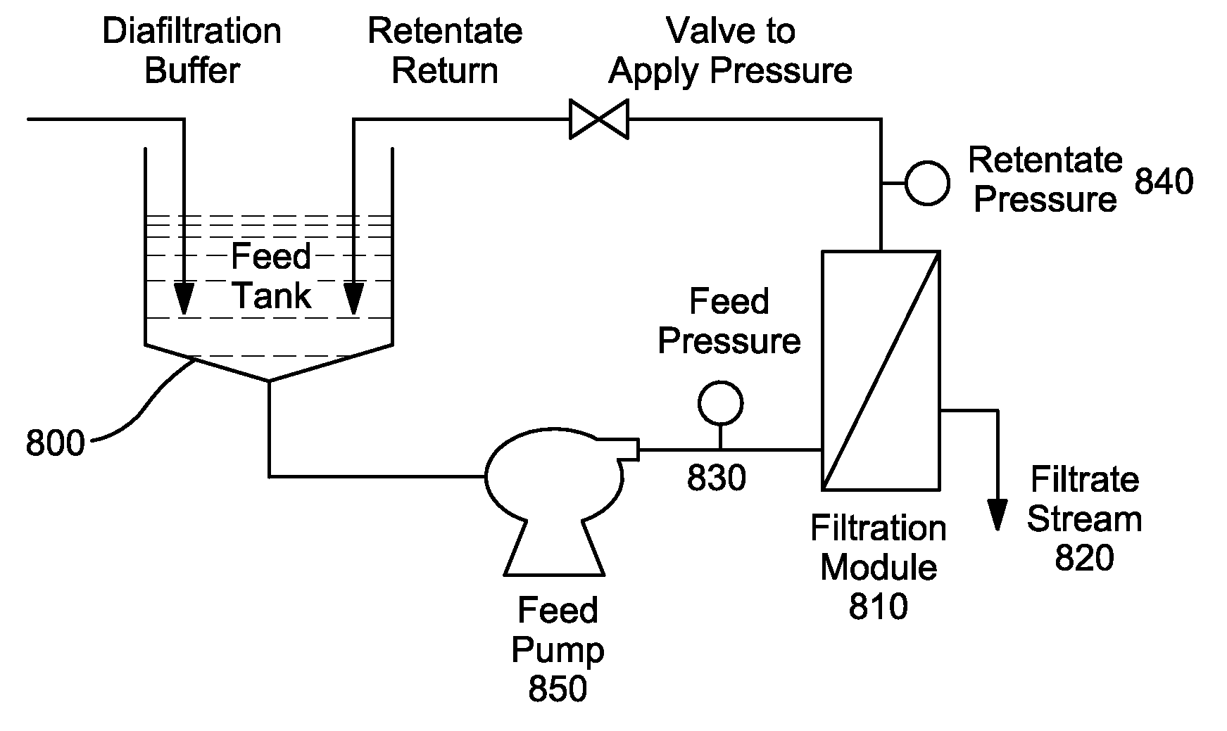
[0105]FIG. 12 shows a traditional concentration TFF system. Fluid from a feed tank 800 is pumped in a circuitous path into a TFF filter 810 and back to the feed tank 800. The TFF filter 810 filters filtrate from the fluid, which exits the system via filtrate stream 820. As this process continues, the concentration of retentate increases. During each pass of fluid over the surface of the filter membrane, the applied pressure forces a portion of the ...


PUM

PropertyMeasurementUnit
Temperatureaaaaaaaaaa
Pressureaaaaaaaaaa
Poweraaaaaaaaaa

Abstract

An autonomous filter device and a method for improving the filter life and performance is disclosed. The filter element is equipped with one or more sensors, adapted to measure one or more characteristics or parameters of the fluid, such as temperature, pressure, or flow rate. In response to the measured characteristic or parameter, the control logic within the filter element is able to determine an appropriate response. For example, the control logic may determine that a sudden, but temporary, blockage has occurred in the filter membrane. In response to this, the control logic may initiate a specific response designed to alleviate the blockage. This response may be a temperature change, a vibration, a change in fluid flow path, or some other action. The control logic will then determine the success of the response, based monitoring any change in the fluid characteristics. Based thereon, the control logic may alert the operator that the filter element must be replaced. Alternatively, if the response was successful in correcting the blockage, the control logic need not notify the operator, as the filter element is back to normal operating operation.

Description

[0001]This application claims priority of U.S. Provisional Patent Application Ser. No. 61 / 152,329, filed Feb. 13, 2009 and U.S. Provisional Patent Application Ser. No. 61 / 241,053, filed Sep. 10, 2009, the disclosures of which are incorporated by reference in their entireties.BACKGROUND OF THE INVENTION[0002]Filters are used in a multitude of applications, from removing crystals from wine, to removing impurities from drinking water and motor oil, to removing particulates from bioreactors, fermentors or other chemical processes.[0003]Filters in each of these applications have issues associated with their use. In some cases, the issues may be specific to a particular application. For example, a number of containers, including but not limited to pharmaceutical containers, such as bioreactors and buffer tanks, require the ability to vent the internal gasses to the outside environment, or to take in fresh gas from outside the container. To do so and maintain sterility, it is common to inc...

Claims


Application Information

Patent Timeline
IPC IPC(8): B01D61/22B01D35/18B01D35/14B01D35/143
CPCB01D61/22B01D63/08B01D65/02B01D2311/103B01D2311/16B01D53/22G01F1/6888G01F1/69G01F15/125B01D65/08B01D2321/40B01D2313/22
Inventor BURKE, AARONDILEO, ANTHONYO'BRIEN, TIMOTHY
Owner MILLIPORE CORP
Why Eureka
Try Eureka