Systems and methods for solar-thermal gasification of biomass

a technology of solar energy and biomass, applied in the field of solar-driven systems, methods and apparatus for refining biomass and other materials, can solve the problems of limited conversion and still lower yield

Inactive Publication Date: 2010-09-23
SUNDROP IP HLDG LLC
View PDF98 Cites 91 Cited by
  • Summary
  • Abstract
  • Description
  • Claims
  • Application Information

AI Technical Summary

Benefits of technology

[0005]Some embodiments relate to a solar-driven chemical plant, including a solar thermal receiver having a cavity with an inner wall, where the solar thermal receiver can be aligned to absorb concentrated solar energy from one or more of 1) an array of heliostats, 2) solar concentrating dishes, and 3) any combination of the two.

Problems solved by technology

Between 30% and 40% of the biomass must be consumed to drive the process, and at the temperatures which the process is generally limited to (for efficiency reasons), conversion is typically limited, giving still lower yields.

Method used


Image

  • Systems and methods for solar-thermal gasification of biomass
  • Systems and methods for solar-thermal gasification of biomass
  • Systems and methods for solar-thermal gasification of biomass

Examples


Embodiment Construction

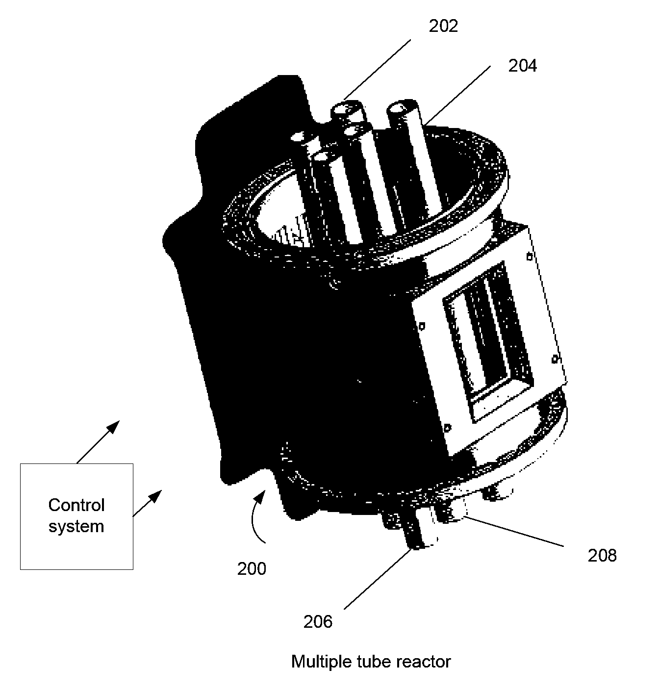
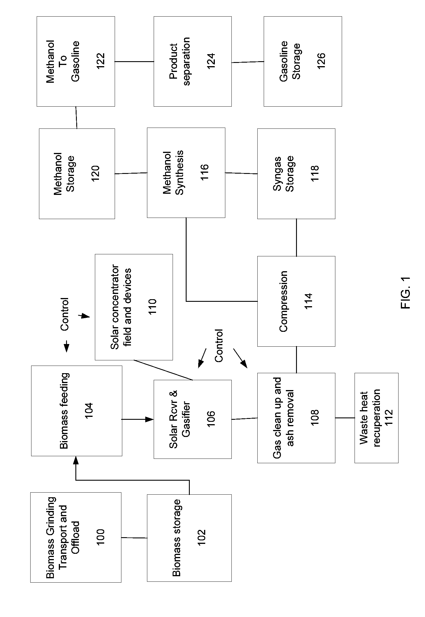
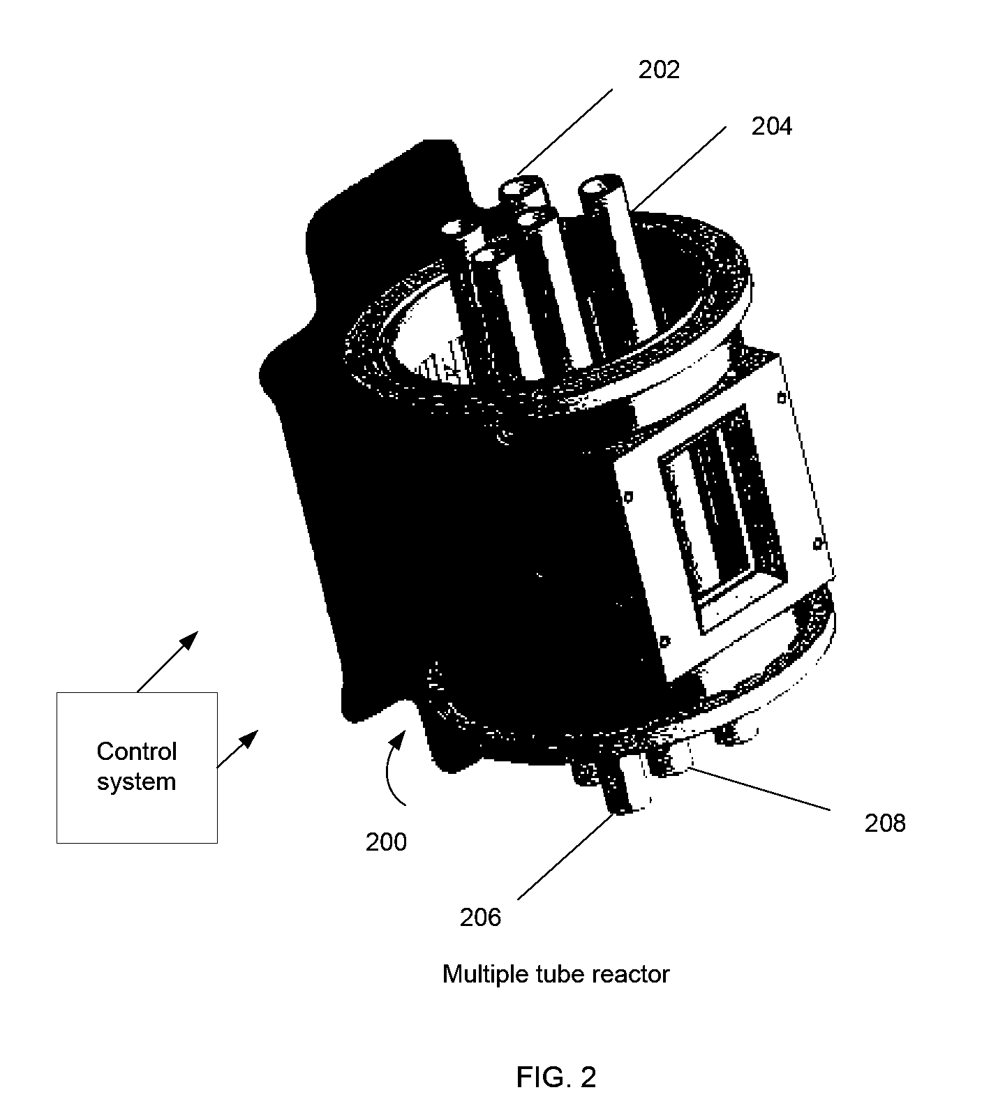
[0018]In the following description, numerous specific details are set forth, such as examples of specific data signals, named components, connections, number of reactor tubes, etc., in order to provide a thorough understanding of the present invention. It will be apparent, however, to one of ordinary skill in the art that the present invention may be practiced without these specific details. In other instances, well known components or methods have not been described in detail but rather in a block diagram in order to avoid unnecessarily obscuring the present invention. Further, specific numeric references such as first reactor tube, may be made. However, the specific numeric reference should not be interpreted as a literal sequential order but rather interpreted that the first reactor tube is different from a second reactor tube. Thus, the specific details set forth are merely exemplary. The specific details may be varied from and still be contemplated to be within the spirit and s...


PUM

PropertyMeasurementUnit
molar ratioaaaaaaaaaa
temperaturesaaaaaaaaaa
diameteraaaaaaaaaa

Abstract

A method, apparatus, and system for a solar-driven chemical plant that may include a solar thermal receiver having a cavity with an inner wall, where the solar thermal receiver is aligned to absorb concentrated solar energy from one or more of 1) an array of heliostats, 2) solar concentrating dishes, and 3) any combination of the two. Some embodiments may include a solar-driven chemical reactor having multiple reactor tubes located inside the cavity of solar thermal receiver, wherein a chemical reaction driven by radiant heat occurs in the multiple reactor tubes, and wherein particles of biomass are gasified in the presence of a steam (H2O) carrier gas and methane (CH4) in a simultaneous steam reformation and steam biomass gasification reaction to produce reaction products that include hydrogen and carbon monoxide gas using the solar thermal energy from the absorbed concentrated solar energy in the multiple reactor tubes.

Description

RELATED APPLICATIONS[0001]This application claims the benefit of both U.S. Provisional Patent Application Ser. No. 61 / 248,282, filed Oct. 2, 2009 and entitled “Various Methods and Apparatuses for Sun Driven Processes,” and U.S. Provisional Patent Application Ser. No. 61 / 185,492, titled “VARIOUS METHODS AND APPARATUSES FOR SOLAR-THERMAL GASIFICATION OF BIOMASS TO PRODUCE SYNTHESIS GAS” filed Jun. 9, 2009, both of which are hereby incorporated herein by reference in their entireties.NOTICE OF COPYRIGHT[0002]A portion of the disclosure of this patent document contains material that is subject to copyright protection. The copyright owner has no objection to the facsimile reproduction by anyone of the software engine and its modules, as it appears in the Patent and Trademark Office Patent file or records, but otherwise reserves all copyright rights whatsoever.FIELD OF THE INVENTION[0003]Embodiments of the invention generally relate to systems, methods, and apparatus for refining biomass ...

Claims


Application Information

Patent Timeline
Patent Type & Authority Applications(United States)
IPC IPC(8): C01B3/02B01J8/04G05D23/00F24S20/20F24S20/30
CPCC01B3/22C10J3/56C01B2203/0216C01B2203/061C01B2203/84C07C29/15C10G2/30C10J3/00C10J3/482C10J3/485C10J3/723C10J2200/09C10J2300/0906C10J2300/0909C10J2300/0916C10J2300/0973C10J2300/0989C10J2300/1284C10J2300/1292C10J2300/1621C10J2300/1659C10J2300/1665C10J2300/1693F24J2/07Y02E10/41Y02E50/18Y02E50/32C01B3/34C10J3/54Y02B40/18C10G2300/1014C10G2300/1025C10G2300/807C07C31/04C07C29/1518C10G2/32C10G3/00C10L1/04C10L2200/0492C10L2290/02C10L2290/04C10L2290/06C10L2290/08C10L2290/28C10L2290/42C10L2290/50C10L2290/52C10L2290/547F24S20/20Y02E10/40Y02E50/10Y02E50/30Y02P20/129Y02P20/133Y02P20/145Y02P20/50Y02P30/20Y02T50/678B01J19/0013B01J19/0033B01J19/2445B01J19/245B01J2219/00117B01J2219/00186C01B3/384C01B2203/0233C01B2203/0811C01B2203/1241C01B2203/1685C10J3/466C10J3/506C10J3/58C10J3/60C10J3/62C10J3/721C10J3/82C10J3/84C10J2200/15C10J2200/158C10J2300/094C10J2300/0976C10J2300/0993C10J2300/1223C10J2300/123C10J2300/1853C10J2300/1861C10K1/024
Inventor SIMMONS, WAYNEPERKINS, CHRISTOPHERJOVANOVIC, ZORAN
Owner SUNDROP IP HLDG LLC
Why Eureka
Try Eureka