
Method of improving the functionality of pole mounted electrical producing or consuming panels

a technology of poles and masts, applied in the direction of lighting support devices, hoisting equipment, lighting and heating apparatus, etc., can solve the problems of device being stuck to the mast, device may not be able to be lowered sufficiently, and vandalism is another threa

Inactive Publication Date: 2010-09-23
MILLER KEVIN L
View PDF6 Cites 20 Cited by
  • Summary
  • Abstract
  • Description
  • Claims
  • Application Information

AI Technical Summary

Benefits of technology

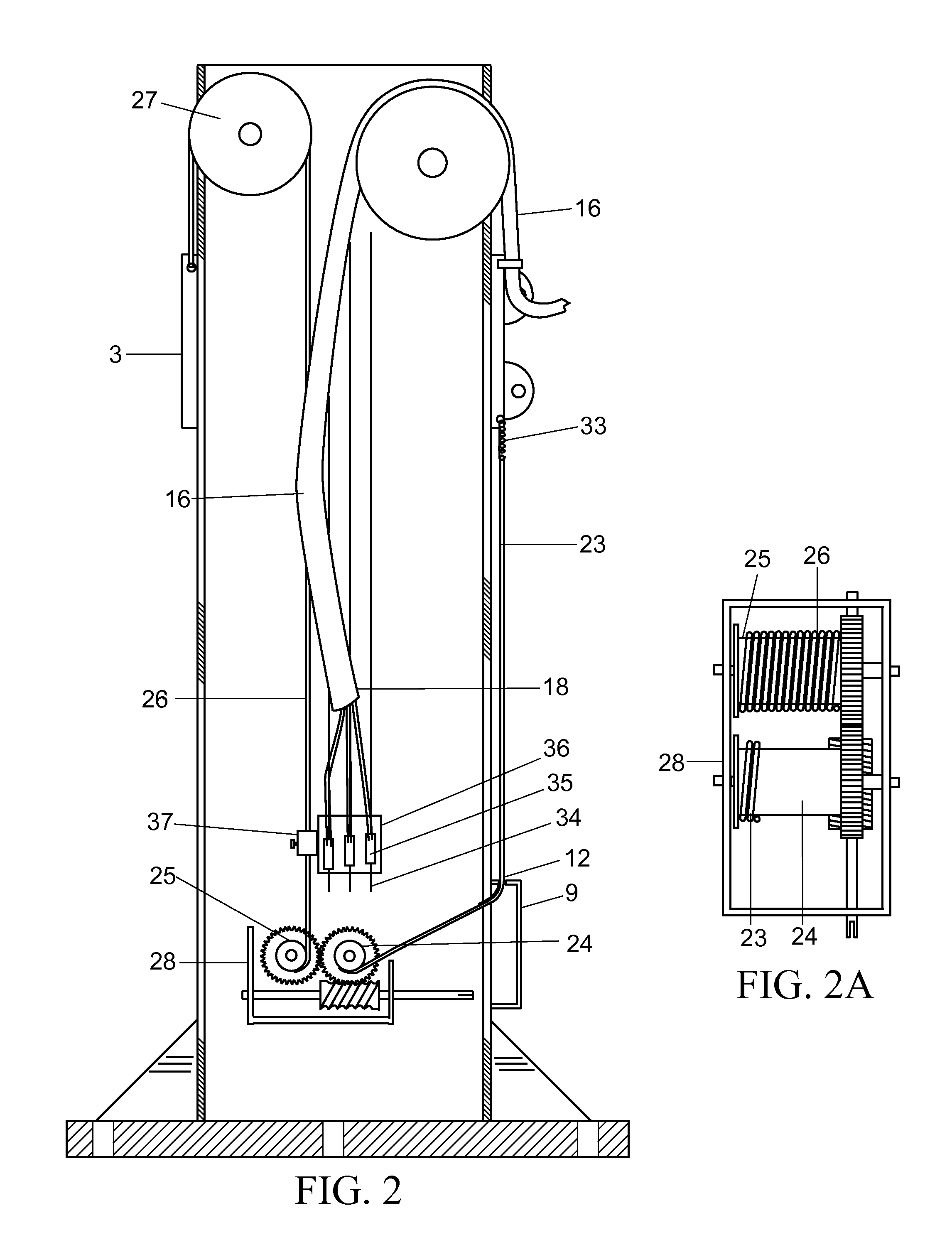
[0006]The present invention describes a method of providing both a positive pull downward as well as upward to a movable device supported by a pole or mast. An improvement is described wherein the coiling of the coiled conductor inside the hollow mast is guided by guy wires thus preventing them from overlapping during the raising cycle of the movable panel. A further improvement is described wherein the coiled conductor is replaced by a shorter straight segment of conductor connected to slidable connectors riding on a rail system inside the mast thus reducing the electrical resistance of the long coil of conductor.

Problems solved by technology

For applications where the device is infrequently lowered or where the device places a substantial side loading on the mast, gravity may not be sufficient to lower the device.
Due to long periods of inactivity, the device may become stuck to the mast due to corrosion, debris or freezing.
Vandalism is another threat so the electrical conductor is typically housed inside a metal mast so it is not exposed.
When raising the panel, the coils often overlap inside the hollow mast causing binding during the next lowering session.
The necessity for the coiled configuration also adds length and thus increased electrical resistance to the circuit, degrading the efficiency of the system.
In this application, the cable movement is typically unequal per revolution of the drum due to the larger effective diameter of one side of the drum caused by the accumulated cable on that side.

Method used


Image

  • Method of improving the functionality of pole mounted electrical producing or consuming panels
  • Method of improving the functionality of pole mounted electrical producing or consuming panels
  • Method of improving the functionality of pole mounted electrical producing or consuming panels

Examples


Embodiment Construction

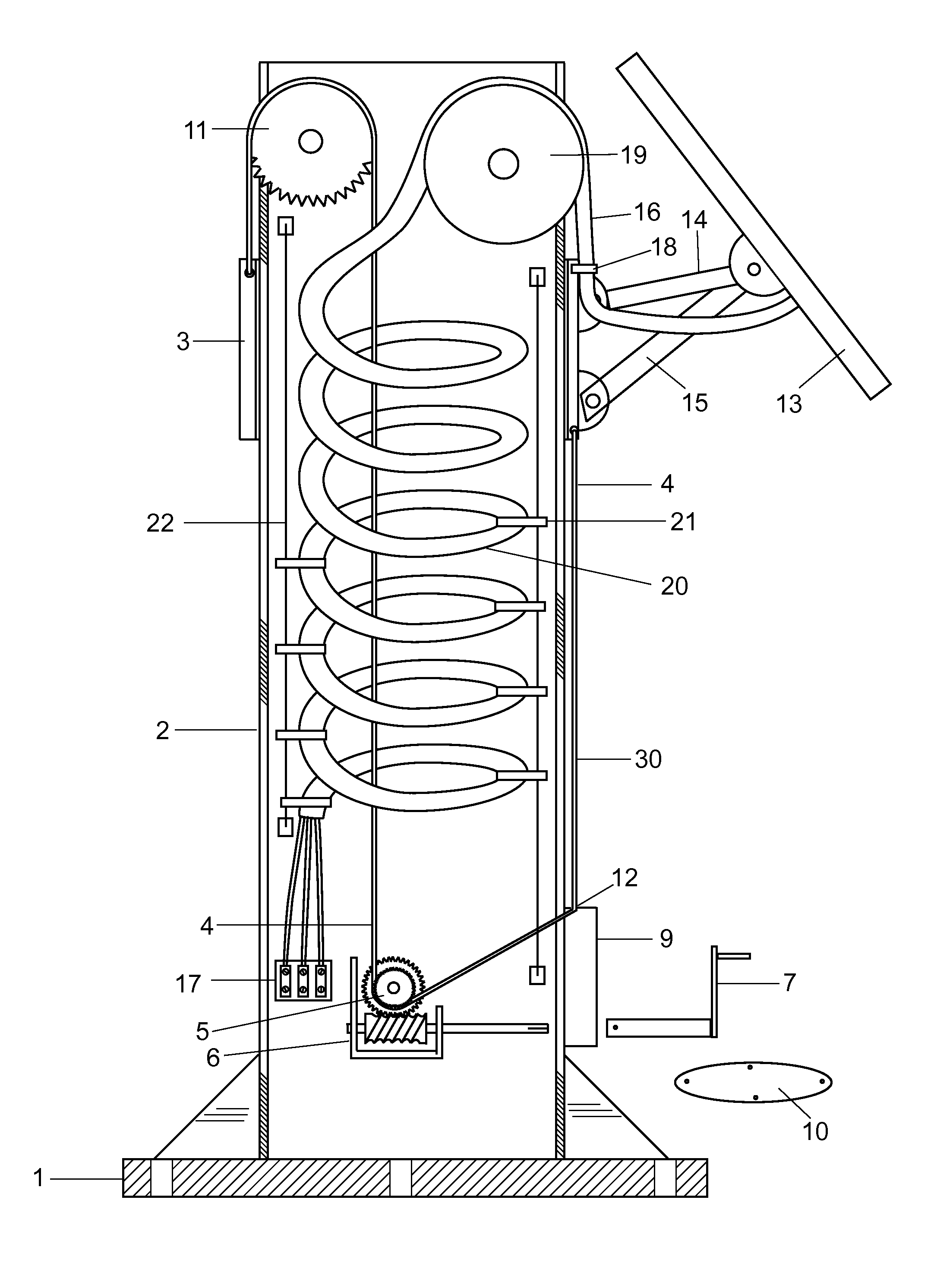
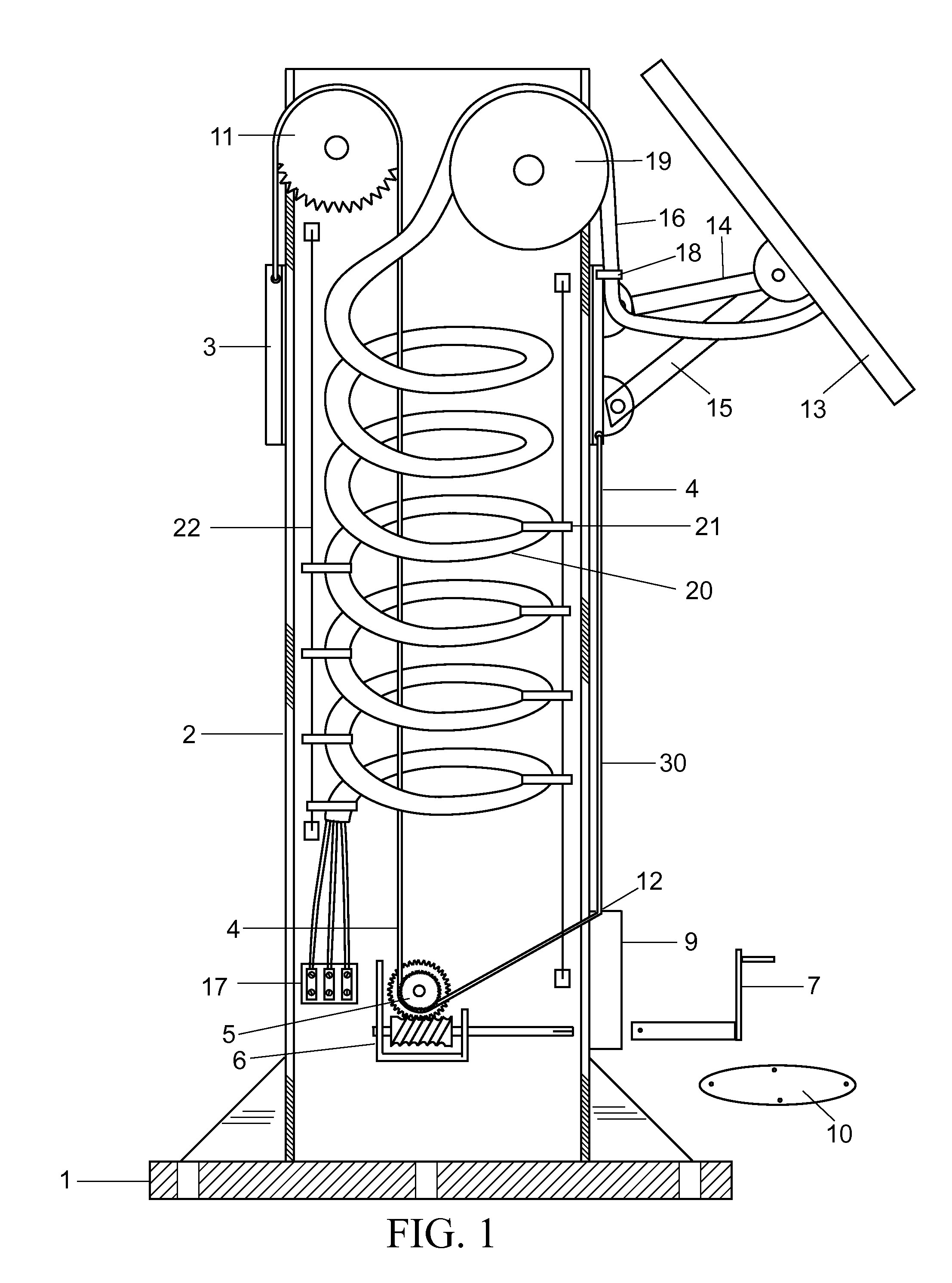
[0013]Referring now to FIG. 1 of the drawings, the said invention consists of a base 1, attached to mast 2 supporting movable device 3 which is caused to move up and down mast 2 by chain 4. Chain 4 is driven by sprocket 5 attached to winch 6 turned by crank 7. Winch 6 is accessible through access hatch 9 once hatch cover 10 is removed. One section of chain 4 passes upward through the center of mast 2, over upper idler sprocket 11 then downward to attach to and thus support movable object 3. The other section of chain 4 leaves winch sprocket 5, exits through a hole 12 in access hatch 9, and extends upward to attach to movable object 3 to provide the downward force needed to lower movable device 3. Electrical panel 13 is supported by brackets 14 and 15 which are attached to movable device 3. Electrical cable 16 conducts derived electrical power to load terminal block 17 in base 1. Electrical cable 16 passes through attachment clamp 18 on movable device 3, up and over upper cable rolle...


PUM


Abstract

Current pole / mast mounted photovoltaic systems rely on gravity to lower the panel down the mast. The energy derived is typically conducted along a coiled conductor that expands or collapses like a spring inside the hollow mast as the movable device, with the solar panel attached, is raised or lowered for maintenance. Due to the large size and stiffness of the coiled conductor, especially in cold weather, the weight of the movable device may not be sufficient to cause the panel to descend when tension on the supporting cable is released. We have developed a method of pulling the sleeve / ring down the mast / pole as well as up. Over long periods of non-use, the sleeve can freeze in position. This new system aids in freeing it up and is also useful when there is un-even side loading on the sleeve. A winch driven chain or cable, attached to the movable device, extending upward to a top roller then internally downward to the winch and then externally extending back up to the movable device, accomplishes this task. A further improvement is a plurality of vertical guide wires and guides attached to the conductor coils that prevent the coils from overlapping in the collapsing mode. An additional improvement is taught wherein the coiled conductor is replaced by a set of conducting rails with a shorter conductor attached to the solar panel.

Description

REFERENCES CITED [0001]U.S. Patent Document5,975,726November 1999Latim er4,115,845September 1978Blahut3,801,813April 1974Keihn3,673,403June 1972WoodsFIELD OF THE INVENTION[0002]This invention is related to pole / mast mounted devices.BACKGROUND OF THE INVENTION[0003]Pole mounted solar panels are placed along remote stretches of railways to power signals and sensors. These are attended infrequently. Prior art for pole / mast mounted devices shows reliance upon gravity to lower the mounted device down the mast for maintenance. For applications where the device is infrequently lowered or where the device places a substantial side loading on the mast, gravity may not be sufficient to lower the device. Due to long periods of inactivity, the device may become stuck to the mast due to corrosion, debris or freezing. A positive means of pulling the device downward is advantageous in these situations. Vandalism is another threat so the electrical conductor is typically housed inside a metal mast ...

Claims


Application Information

Patent Timeline
IPC IPC(8): B66D1/20B66D1/00
CPCB66F7/02F21V21/22F21V21/38F21V27/00F24J2/523H02S20/00F24J2/5264F24J2/5266Y02E10/47Y02E10/50F24J2/5241H02S20/30H02S20/10F24S30/20F24S25/50F24S25/10F24S25/70
Inventor MILLER, KEVIN L.
Owner MILLER KEVIN L
Learn More