Inverter controller, and motor driving device, electric compressor and electric home appliance using the inverter controller

a technology of inverter controller and motor driving device, which is applied in the direction of motor/generator/converter stopper, electronic commutator, dynamo-electric converter control, etc. it can solve the problems of low voltage between the respective terminals of the brushless dc motor, narrow the working range of the inverter, and low utilization rate, so as to reduce the conduction angle and improve the responsiveness to changes. , the effect of enlarging th

Active Publication Date: 2010-09-23
PANASONIC APPLIANCES REFRIGERATION DEVICES SINGAPORE
View PDF5 Cites 34 Cited by
  • Summary
  • Abstract
  • Description
  • Claims
  • Application Information

AI Technical Summary

Benefits of technology

[0038]The present invention provides a reliable inverter controller which changes instantaneously a conduction angle in response to a change in voltage of a DC voltage section, thereby preventing a brushless DC motor from falling in out-of-synchronous and stopping its work due to an instantaneous power interruption or an abrupt change in voltage. The present invention also provides motor driving devices, electric compressors, and electric home appliances using the inverter controller. The inverter controller of the present invention drives a brushless DC motor, of which rotor includes permanent magnets. The inverter controller has an inverter circuit, a position sensing circuit, a DC voltage sensor, and a conduction angle controller. The inverter circuit is coupled to and drives the brushless DC motor. The position sensing circuit senses a position of the rotor with respect to a stator from an induction voltage of the brushless DC

Problems solved by technology

During this non-controlled period, the inverter fails to output a desired voltage, so that the inverter uses the DC voltage at a low utilization rate.
This low utilization rate causes a low voltage between the respective terminals of the brushless DC motor as well as narrows the working range of the inverter.
However, since circuit 010 employs a filter, a delay of 90 degrees in electric angles occurs, which causes a lower responsiveness to a variation in rotational speed such

Method used


Image

  • Inverter controller, and motor driving device, electric compressor and electric home appliance using the inverter controller
  • Inverter controller, and motor driving device, electric compressor and electric home appliance using the inverter controller
  • Inverter controller, and motor driving device, electric compressor and electric home appliance using the inverter controller

Examples


Embodiment Construction

[0051]An exemplary embodiment of the present invention is demonstrated hereinafter with reference to the accompanying drawings. Not to mention, this embodiment does not limit the present invention.

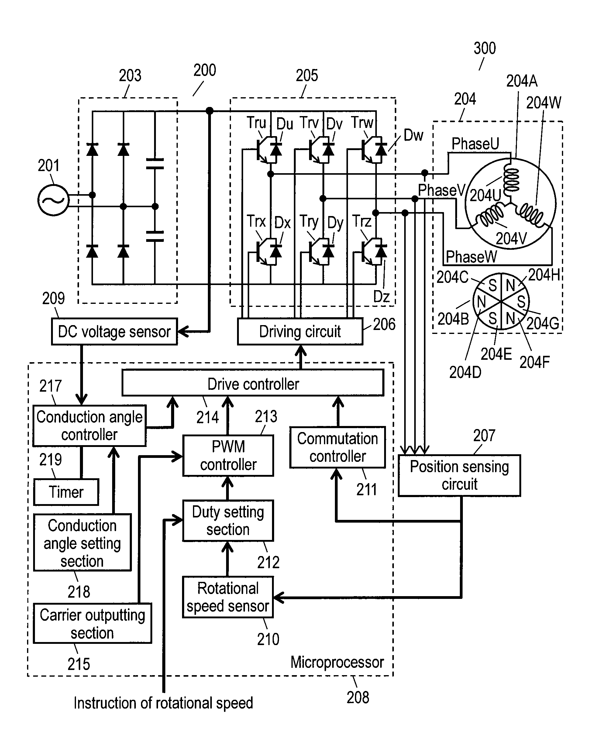
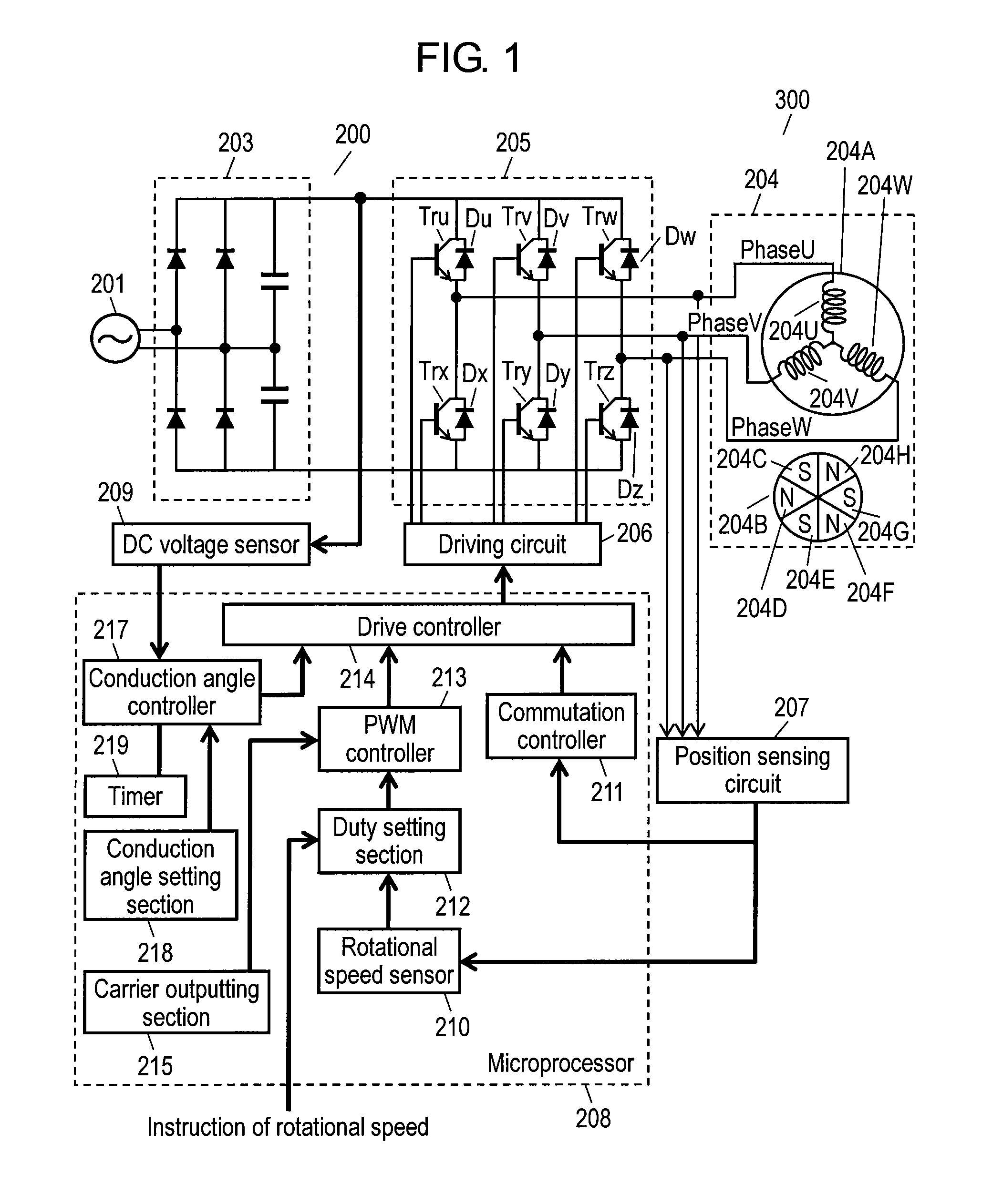
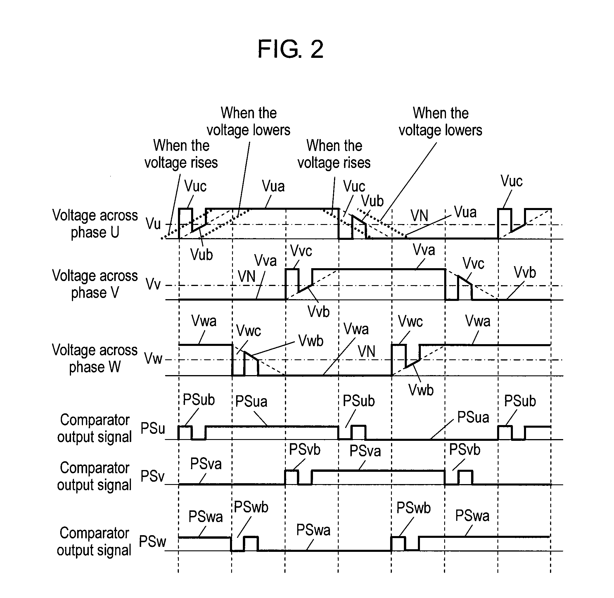
[0052]FIG. 1 shows a structure of an inverter controller in accordance with this embodiment of the present invention. FIG. 2 is a timing chart showing waveforms of respective sections in the inverter controller and timing the processes done by the respective sections. FIG. 3 shows characteristics indicating the relation between conduction angles and voltage variations in a power supply of the inverter controller. FIG. 4 is a timing chart showing operation of the inverter controller when a voltage changes in the inverter controller.

[0053]As shown in FIG. 1, inverter controller 200 is coupled to commercial AC power supply 201 and brushless DC motor (hereinafter simply referred to as “motor”) 204, and drives motor 204. Inverter controller 200 and motor 204 thus form motor driving device 300. ...


PUM


Abstract

An inverter controller for driving a brushless DC motor, of which rotor is provided with permanent magnets, includes an inverter circuit, a position sensing circuit, a DC voltage sensor, and a conduction angle controller. The inverter circuit is connected to the brushless DC motor for driving this motor. The position sensing circuit senses a rotor position with respect to a stator from an induction voltage of the brushless DC motor. The DC voltage sensor senses a voltage value of a DC power voltage supplied to the inverter circuit. The conduction angle controller changes a conduction angle of the inverter circuit within a range less than 180 degrees in electric angles in response to a rate of change in the DC power voltage.

Description

[0001]This application is a u.s. National Phase application of PCT International Application PCT / JP2008 / 003549.TECHNICAL FIELD[0002]The present invention relates to a wide-angle conduction control method employed in an inverter controller for a brushless DC motor, and it also relates to motor driving devices, electric compressors, electric home appliances such as a refrigerator, using the inverter controller.BACKGROUND ART[0003]As control over the waveform of an inverter, 120-degree conduction waveforms is generally adopted from the viewpoint of simplicity in control. In a driving system for a brushless DC motor, switches of respective phases of the inverter are electrically conducted within 120 degrees in electrical angles although the electrical angle is spanned as wide as 180 degrees both on positive side and negative side respectively. No control is thus done in the remaining period of 60 degrees in electrical angles. During this non-controlled period, the inverter fails to outp...

Claims


Application Information

Patent Timeline
IPC IPC(8): H02P6/18H02P6/14
CPCH02P6/142H02P29/026H02P6/182H02P6/147H02P6/15H02P6/157
Inventor OGAHARA, HIDEHARU
Owner PANASONIC APPLIANCES REFRIGERATION DEVICES SINGAPORE
Why Eureka
Try Eureka