Array antenna and radar apparatus
a radar and array antenna technology, applied in the direction of non-resonant long antennas, instruments, and reradiation, can solve the problems of insufficient adjustment of tilt angle, circuit scale and signal processing amount of radar apparatus to increase, etc., and achieve the effect of wide range without increasing circuit scale or signal processing amoun
- Summary
- Abstract
- Description
- Claims
- Application Information
AI Technical Summary
Benefits of technology
Problems solved by technology
Method used
Image

Examples
first embodiment
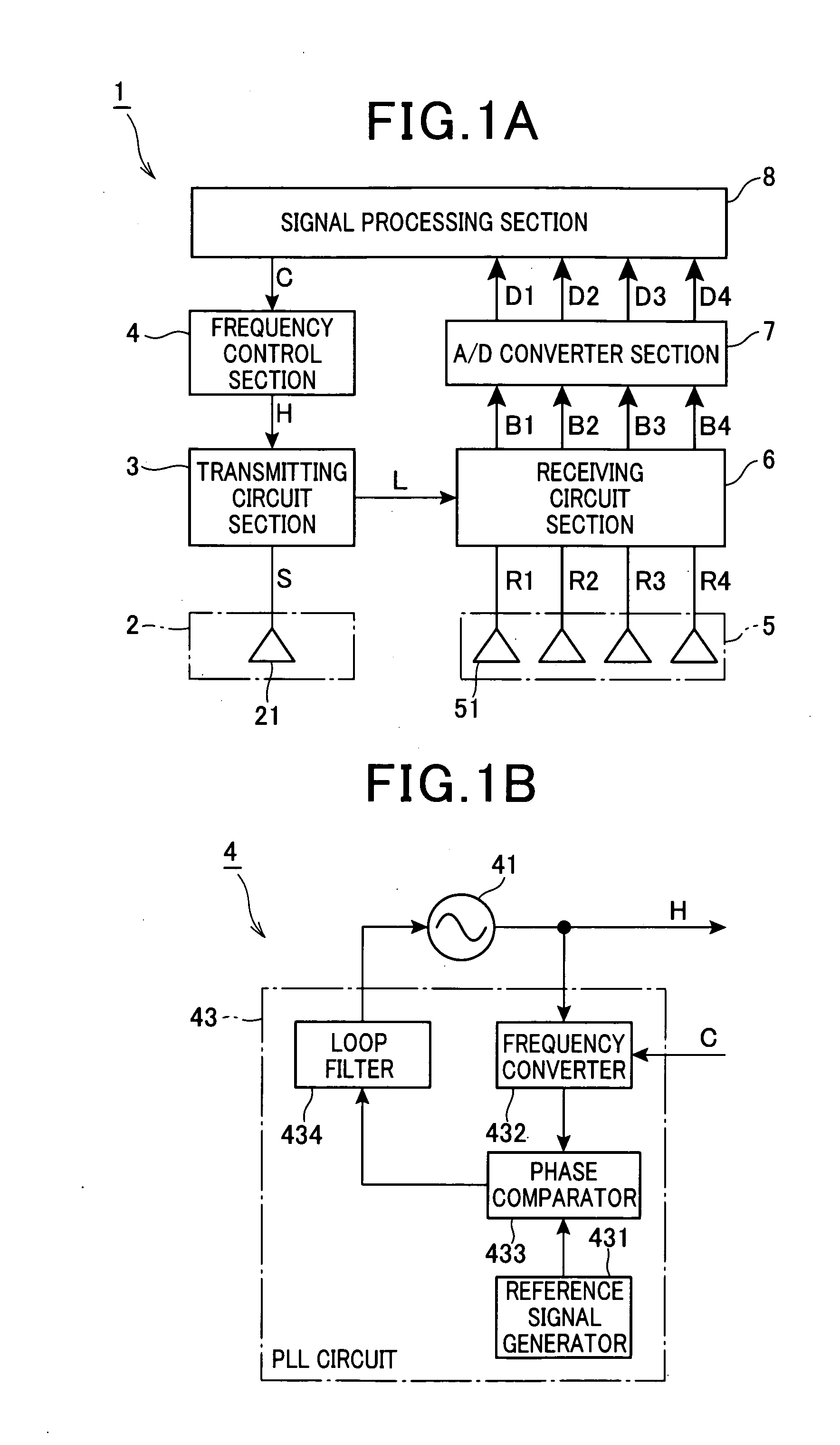
[0041]FIG. 1 is a block diagram showing the overall structure of a radar apparatus 1 to which the present invention is applicable.
[0042]As shown in FIG. 1, the radar apparatus 1 includes a transmitting antenna section 2, a frequency control section 4, a transmitting circuit section 3, a receiving antenna section 5, a receiving circuit section 6, an A / D converter section 7, and a signal processing section 8.
[0043]The transmitting antenna section 2 transmits a radar beam of a millimeter-wave band (76 GHz to 77 GHz, in this embodiment). The frequency control section 4 generates a high frequency signal H of the millimeter-wave band, and controls the frequency of this high frequency signal H in accordance with a control command C received. The transmitting circuit section 3 distributes the high frequency signal H generated by the frequency control section 4 to the transmitting antenna section 2 as a transmit signal S, and to the receiving circuit section 6 as a local signal L. The receiv...
second embodiment
[0068]Next, a second embodiment of the invention is described. Since the second embodiment differs from the first embodiment only in that the transmitting antenna section 2 and the receiving antenna section 5 are constituted of array antennas 121, the following description focuses on the structure of the array antenna 121.
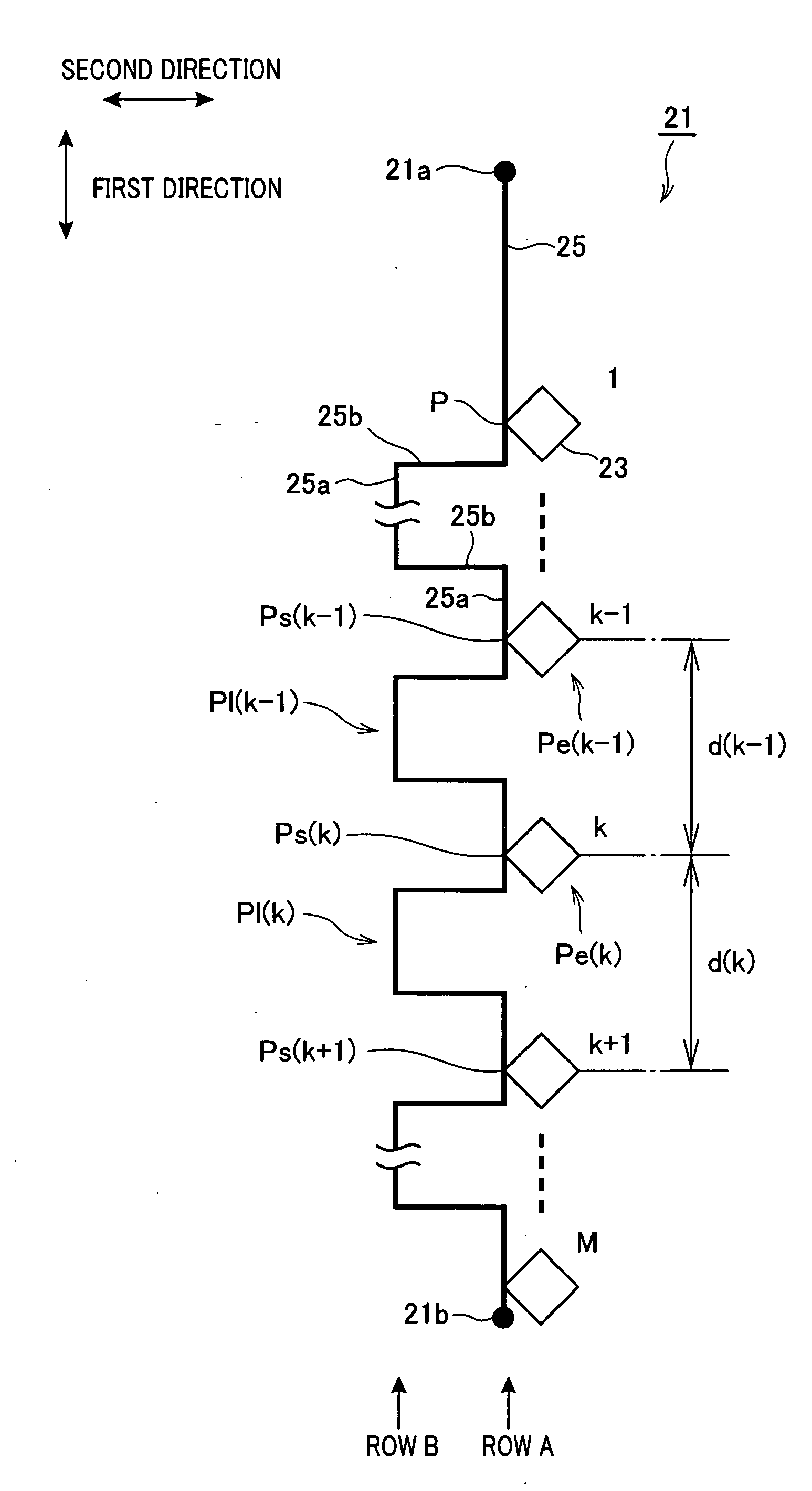
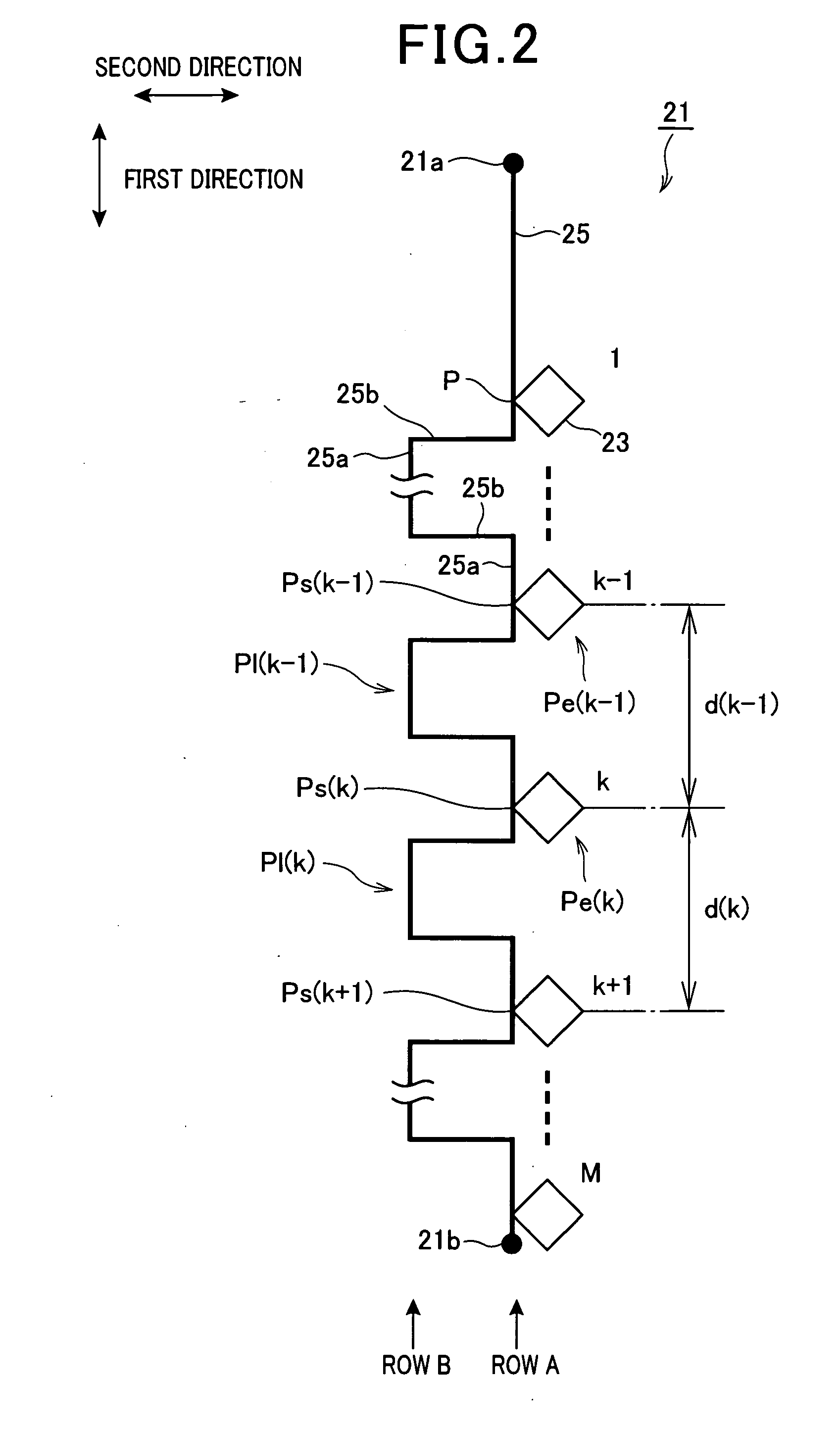
[0069]FIG. 5A is a diagram schematically showing the arrangement of the radiating elements 23 and 25 and feed line 25 constituting the array antenna 121 of the second embodiment. As shown in FIG. 5A, the feed line 25 in this embodiment has the same configuration as that in the first embodiment.
[0070]In the first embodiment, the radiating elements 23 are arranged in a row extending along the first direction, and fed from the partial feed lines 25a on the row A which constitute the first partial feed line group together with the row B. On the other hand, in the second embodiment, the radiating elements 23 are arranged in two rows extending along the first direction, ...
third embodiment
[0074]Next, a third embodiment of the invention is described. Since the third embodiment differs from the first embodiment only in that the transmitting antenna section 2 and the receiving antenna section 5 are constituted of array antennas 221, the following description focuses on the structure of the array antenna 221.
[0075]FIG. 6A is a diagram schematically showing the arrangement of the radiating elements 23 and the feed line 25 constituting the array antenna 221 of this embodiment. As shown in this figure, the feed line 25 of the array antenna 221 is laid in a shape of a series of cranks as in the case of the first embodiment. However, in this embodiment, the length of the respective partial feed lines 25a belonging to the first partial feed line group is set equal to λg, while the length of the respective partial feed lines 25b belonging to the second partial feed line group is set equal to 3λg.
[0076]Further, each of the partial feed lines 25b belonging to the second partial f...
PUM
 Abstract
Description
Claims
Application Information
 - R&D
- Intellectual Property
- Life Sciences
- Materials
- Tech Scout
- Unparalleled Data Quality
- Higher Quality Content
- 60% Fewer Hallucinations
Browse by: Latest US Patents, China's latest patents, Technical Efficacy Thesaurus, Application Domain, Technology Topic, Popular Technical Reports.
© 2025 PatSnap. All rights reserved.Legal|Privacy policy|Modern Slavery Act Transparency Statement|Sitemap|About US| Contact US: help@patsnap.com