Display device and method for driving display device

a display device and display technology, applied in the field of matrix display devices, can solve the problems of delay in the output of gate pulses subsequent to the gsp signal, inability to adequately charge the pixels on the dummy line g, and inability to provide an adequate effect as a dummy line, etc., to achieve the effect of reducing the cost and circuit area, and preventing the deterioration of display quality

Inactive Publication Date: 2010-09-23
SHARP KK
View PDF18 Cites 20 Cited by
  • Summary
  • Abstract
  • Description
  • Claims
  • Application Information

AI Technical Summary

Benefits of technology

[0054]Therefore, the present invention makes it possible to equalize the parasitic capacitances generated in each of the pixels but to cause no increase in cost a...

Problems solved by technology

For this reason, it is not possible to adequately charge the pixels on the dummy line G0.
As a result, the dummy line cannot provide an adequate effect as a dummy line.
However, in the technique of Patent ...

Method used


Image

  • Display device and method for driving display device
  • Display device and method for driving display device
  • Display device and method for driving display device

Examples


Embodiment Construction

[0110]In the following, an embodiment of the present invention is described with reference to FIGS. 1 to 5.

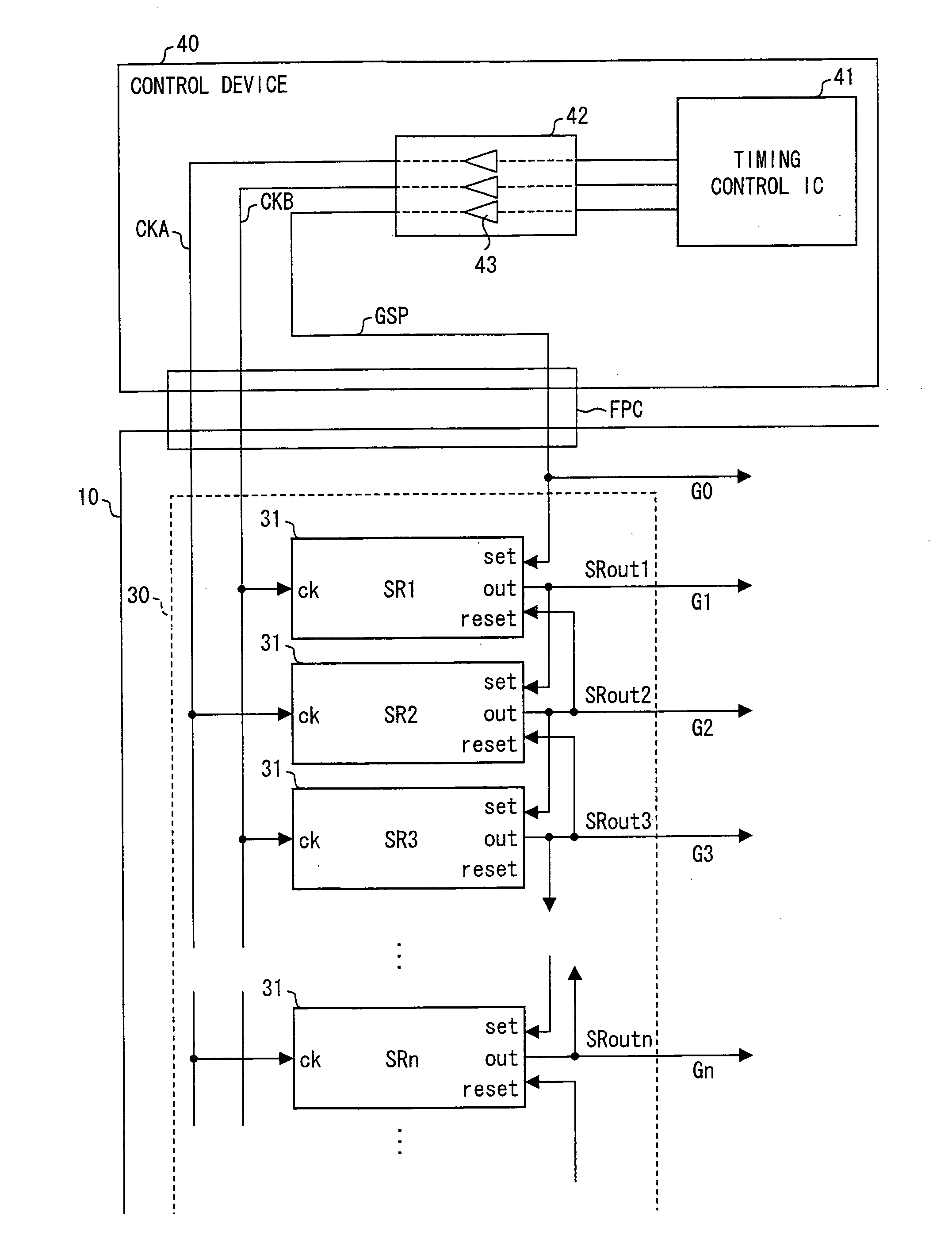
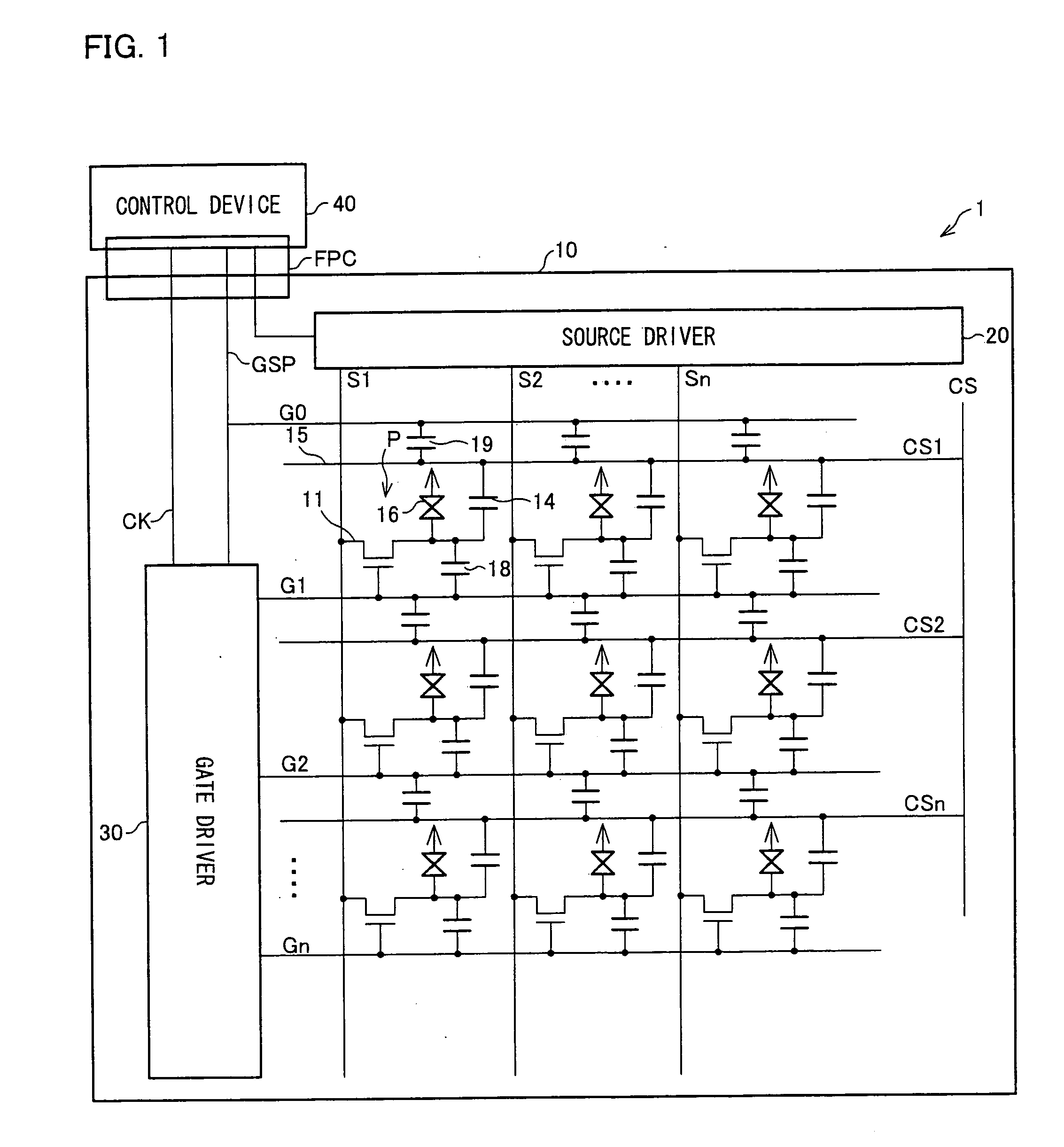
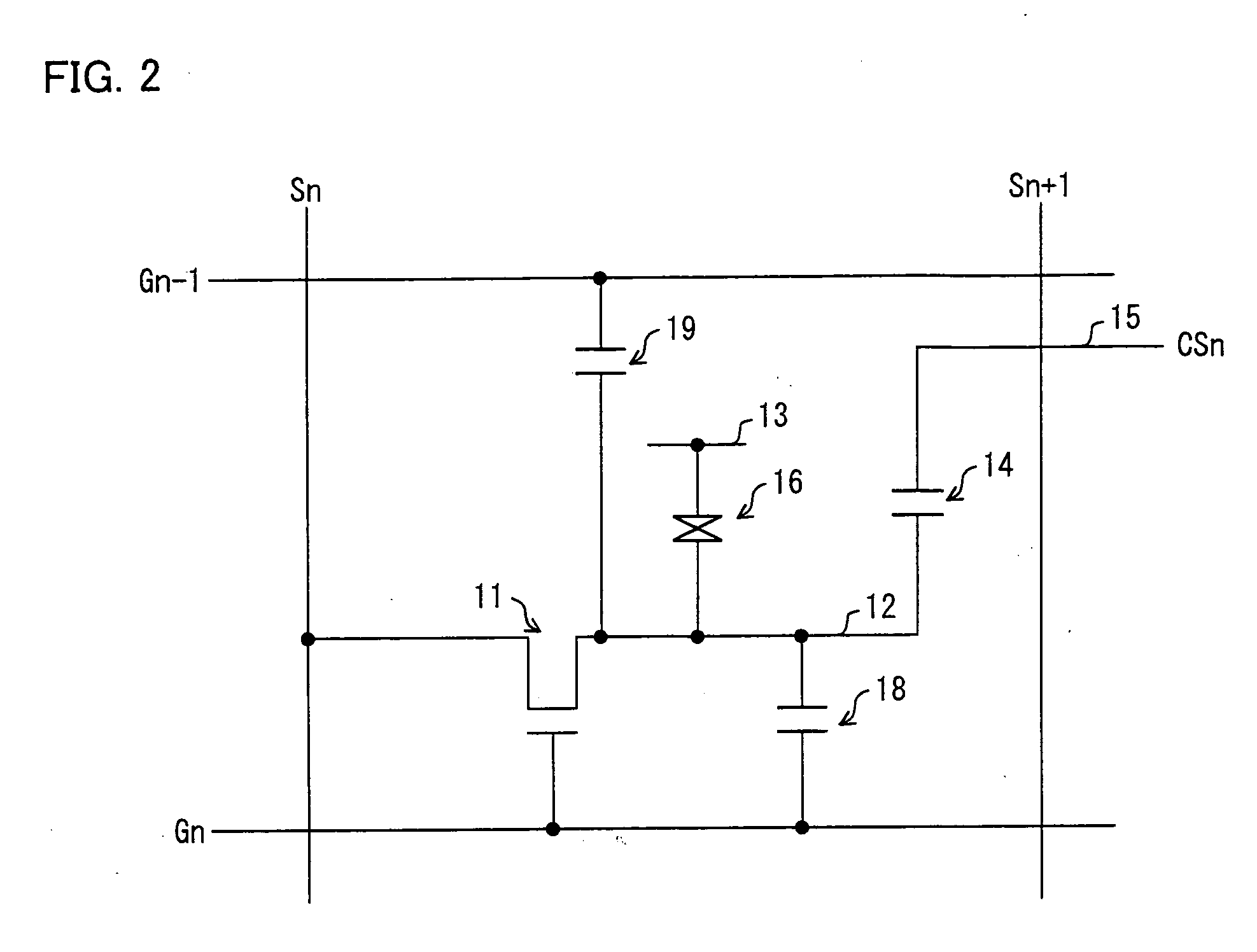
[0111]First, with reference to FIGS. 1 and 2, the following describes a configuration of a liquid crystal display device 1 which corresponds to a display device of the present invention. FIG. 1 is a block diagram illustrating an entire configuration of the liquid crystal display 1. FIG. 2 is an equivalent circuit diagram illustrating an electrical configuration of a pixel of the liquid crystal display device 1. Note that, in a configuration of a liquid crystal display device, in many cases, the terms “row” and “horizontal” express a sequence in a lateral direction of a display panel and the terms “column” and “vertical” express a sequence in a longitudinal direction of a display panel. However, the definitions are not necessarily limited thereto, and the lateral and longitudinal directions in the definitions may be reversed. As such, in the present invention, the terms “row”, “...


PUM


Abstract

A display device, in at least one embodiment, includes: a gate driver including a plurality of shift register stages each provided so as to correspond to each row, the gate driver outputting a gate signal for turning on switching elements in the each row; and a source driver outputting a data signal in accordance with an image to be displayed. For a row (first row) located at an outermost position from which scanning by use of the gate signal starts, a dummy line is provided. The dummy line is driven by a gate start pulse inputted into a shift register in the first row.

Description

TECHNICAL FIELD[0001]The present invention relates to a matrix display device and a method for driving the matrix display device.BACKGROUND ART[0002]Commonly known matrix display devices are, for example, a liquid crystal display device including an active matrix substrate, on which TFTs (Thin Film Transistors) are formed, and driver ICs (Integrated Circuits) for driving the TFTs.[0003]FIG. 6 illustrates a TFT active matrix liquid crystal display device 101. The liquid crystal display device 101 is provided with a gate driver 102 and a source driver 103. The gate driver 102 is a circuit for driving rows of a matrix, and the source driver 103 is, a circuit for driving columns of the matrix.[0004]On a transparent substrate, a plurality of gate lines Gn, Gn+1, . . . (hereinafter denoted by a reference sign G, when collectively termed) and a plurality of source lines Sn, Sn+1, . . . (hereinafter denoted by a reference sign S, when collectively termed) are formed so as to orthogonally in...

Claims


Application Information

Patent Timeline
IPC IPC(8): G06F3/038
CPCG09G3/3648G09G3/3677G09G2300/043G09G2320/0219G09G2310/0286G09G2310/08G09G2300/0876
Inventor IWAMOTO, AKIHISAMORII, HIDEKIMIZUNAGA, TAKAYUKIHIROKANE, MASAHIROOHTA, YUUKI
Owner SHARP KK
Why Eureka
Try Eureka