Method for positioning biological samples in a microscopic arrangement

a technology for positioning biological samples and microscopic arrangement, which is applied in the direction of withdrawing sample devices, instruments, material analysis, etc., to achieve the effect of high efficiency

Active Publication Date: 2010-09-23
CARL ZEISS MICROSCOPY GMBH
View PDF7 Cites 13 Cited by
  • Summary
  • Abstract
  • Description
  • Claims
  • Application Information

AI Technical Summary

Benefits of technology

[0012]Therefore, it is the object of the invention to propose methods and devices which make it possible to position at least one preferably biological specimen in the specimen space of a microscope arrangement with high efficiency.
[0021]This embodiment not only has the advantage that the specimen located in the cutout moves relatively freely and can also continue to grow in circumference, but it can also be removed from the gel body again after observation and / or detection and is accordingly available for further analyses.
[0026]In another special embodiment, the gel body is initially heated in the area of a cutout in which a specimen is to be inserted, the specimen is then inserted, whereupon a medium which is initially liquid but which then hardens is introduced into the cutout, whereupon the gel body is cooled in the area of this cutout which has already been charged with the specimen and filled with the hardening medium in order to accelerate hardening or shorten the duration of the hardening process to a predetermined time period.
[0027]In this connection, it is again advantageous when the gel body is heated in the area of a first cutout within a given time interval and the specimen is then inserted into this cutout and the hardening medium is introduced into this cutout, while the gel is heated in the area of a second cutout at the same time, whereupon the gel is cooled in the area of the first cutout, while the specimen is inserted at the same time into the second cutout, the hardening medium is introduced, and the gel is preheated in the area of a third cutout, whereupon the gel is cooled in the area of the second cutout, while the specimen is insetted at the same time into the third cutout, the hardening medium is introduced, and the gel is preheated in the area of a third cutout, and so on until a specimen is contained and fixed in every cutout.
[0057]It is also advantageous when a syringe is associated with the cutting device for feeding an individual specimen into a cutout. It is possible to charge the pre-shaped gel bodies with specimens in a time-saving manner by cutting out the cutout and inserting the specimen in one and the same position virtually in immediate succession.

Problems solved by technology

Often, it is problematic to position the specimens in the specimen space in such a way that the image information obtained from the specimen coincides in spite of frequent changes in the detection direction so that a high-quality 3D image can be calculated therefrom.

Method used


Image

  • Method for positioning biological samples in a microscopic arrangement
  • Method for positioning biological samples in a microscopic arrangement
  • Method for positioning biological samples in a microscopic arrangement

Examples


Embodiment Construction

[0070]It is to be understood that the figures and descriptions of the present invention have been simplified to illustrate elements that are relevant for a clear understanding of the present invention, while eliminating, for purposes of clarity, many other elements which are conventional in this art. Those of ordinary skill in the art will recognize that other elements are desirable for implementing the present invention. However, because such elements are well known in the art, and because they do not facilitate a better understanding of the present invention, a discussion of such elements is not provided herein.

[0071]The present invention will now be described in detail on the basis of exemplary embodiments.

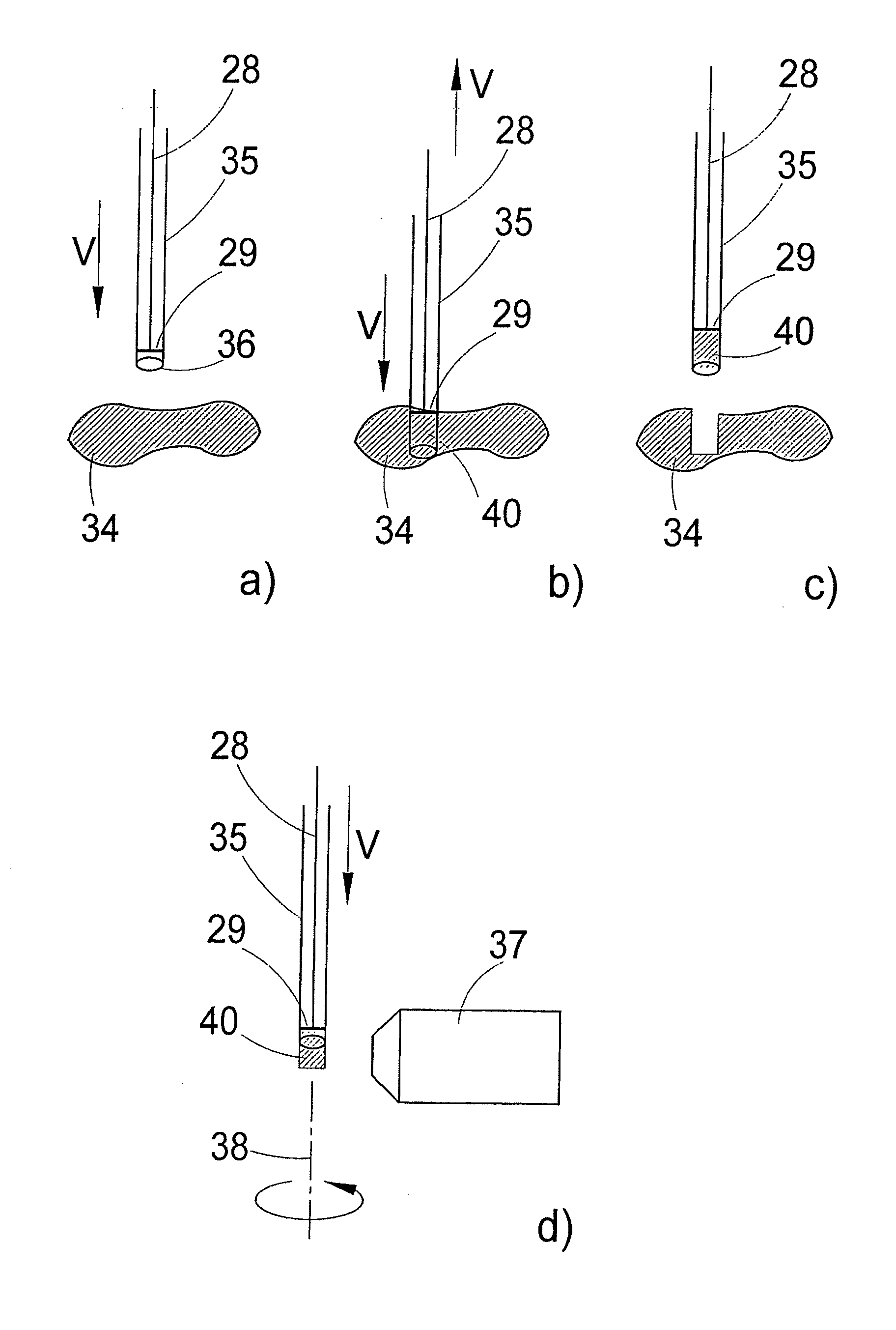
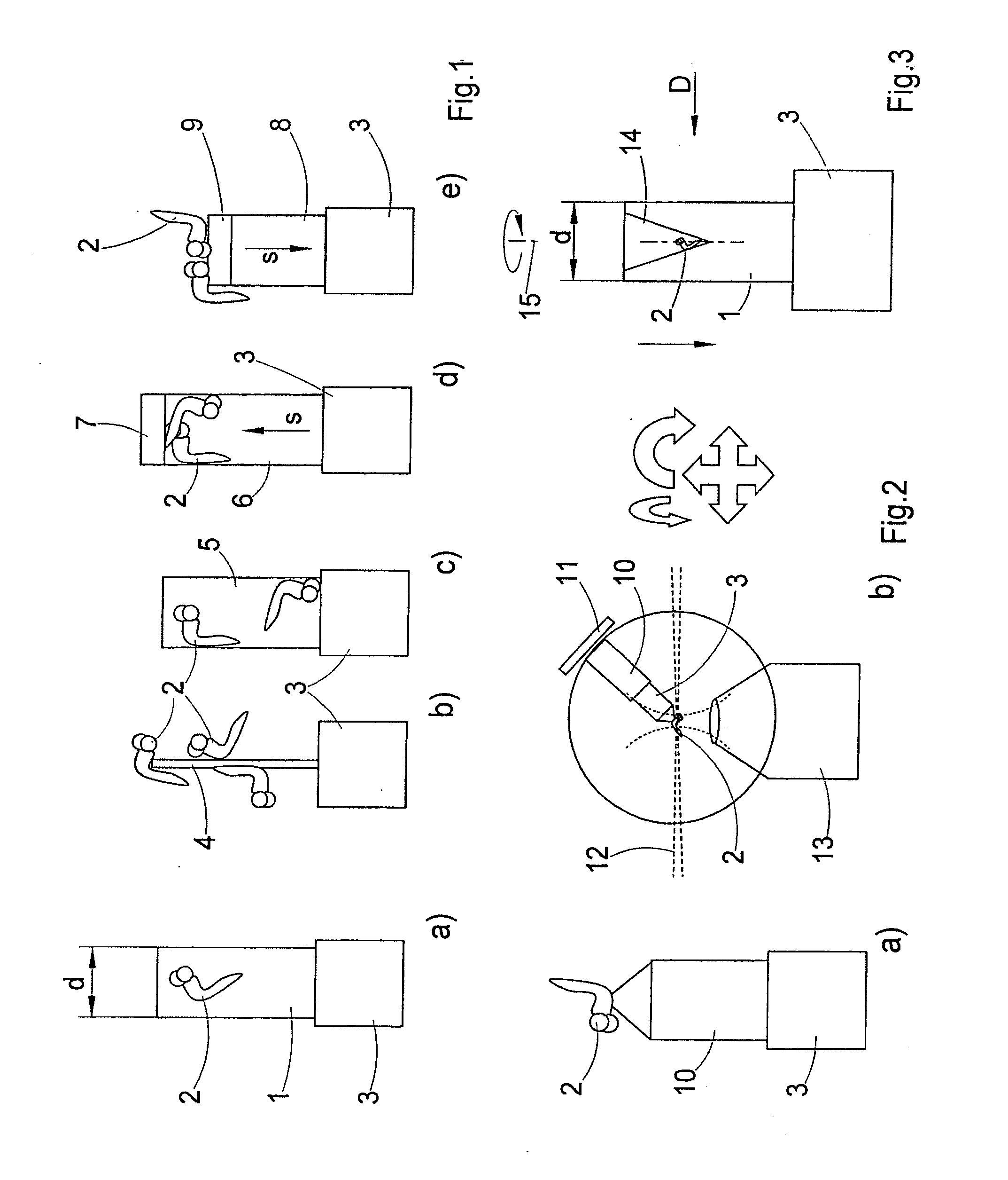
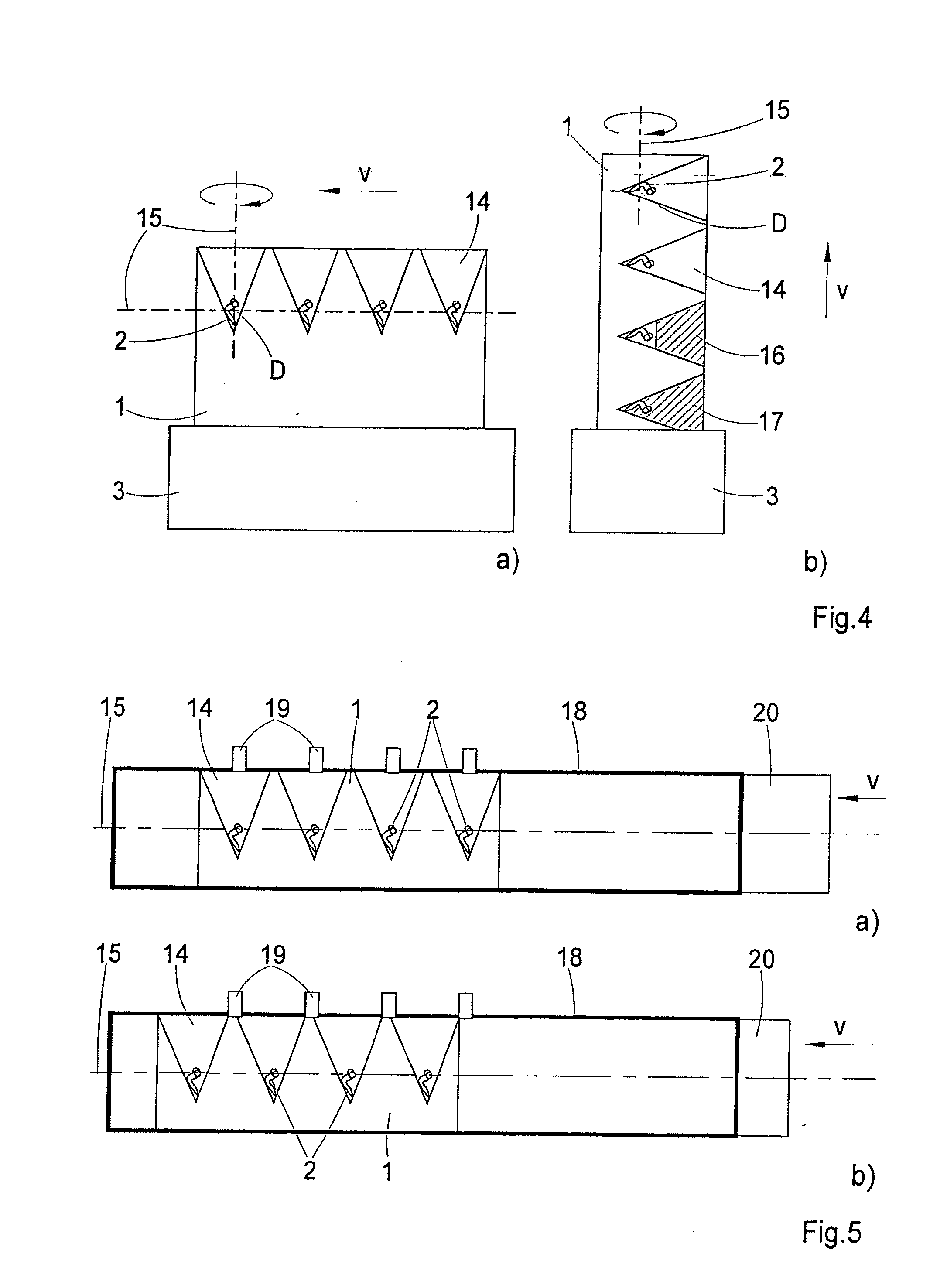
[0072]FIG. 1 shows various embodiment examples for non-destructive positioning of a biological specimen in the specimen space of a microscope arrangement, preferably for obtaining a three-dimensional image of the specimen, particularly by single plane illumination microscopy (S...


PUM

PropertyMeasurementUnit
degrees of freedomaaaaaaaaaa
refractive indexaaaaaaaaaa
adhesive forcesaaaaaaaaaa

Abstract

The invention relates to methods for positioning at least one preferably biological specimen in the specimen space of a microscope arrangement, and to devices for carrying out these methods. Methods and devices are proposed, wherein the specimen's orientation relative to a detection objective's optical axis can be repeatedly changed and, in doing so, the specimen is held so that a substantially unobstructed view of the specimen is ensured from every detection direction. In different constructional variants, the specimen is held at a supporting device by adhesive forces or by a flowing medium, the specimen is held at a capillary opening by capillary action, or at least one specimen is embedded in a body of transparent gel, and the gel body is fixed in the specimen space by means of a rotatable holding device, and the detection direction is changed by rotating the holding device by a given angle of rotation.

Description

[0001]The present application claims priority from PCT Patent Application No. PCT / EP2008 / 007785 filed on Sep. 18, 2008, which claims priority from German Patent Application No. DE 10 2007 048 409.9 filed on Oct. 9, 2007, the disclosure of which is incorporated herein by reference in its entirety.BACKGROUND OF THE INVENTION[0002]1. Field of the Invention[0003]The invention is directed to methods for positioning at least one preferably biological specimen in the specimen space of a microscope arrangement. The subject matter of the invention further relates to devices for applying these methods.[0004]The specimen holder according to the invention can be applied particularly in connection with single plane illumination microscopy (SPIM), also known as selective plane illumination microscopy. Whereas in confocal laser scanning microscopy the specimen is scanned point by point in a plurality of planes at different depths and three-dimensional image information about the specimen is obtain...

Claims


Application Information

Patent Timeline
Patent Type & Authority Applications(United States)
IPC IPC(8): G06K9/00G01N1/00
CPCG02B21/34
Inventor LIPPERT, HELMUTRADT, BENNODIETRICH, CHRISTIANPOWER, CHRISTOPHER
Owner CARL ZEISS MICROSCOPY GMBH
Why Eureka
Try Eureka