Image forming apparatus

a technology of image forming apparatus and charging member, which is applied in the direction of electrographic process apparatus, instruments, etc., can solve the problems of deterioration of image bearing member such as abrasion (wearing) of image bearing member, inability to maintain constant relationship between voltage applied to charging member and electric discharge amount, etc., to suppress the effect of lowering the productivity of an imag

Inactive Publication Date: 2010-09-23
CANON KK
View PDF4 Cites 27 Cited by
  • Summary
  • Abstract
  • Description
  • Claims
  • Application Information

AI Technical Summary

Benefits of technology

[0024]A principal object of the present invention is to provide an image forming apparatus, using different charging frequencies adapted to different process speeds, capable of setting a proper charging voltage while suppressing a lowering in productivity of an image.

Problems solved by technology

In the AC charging method, compared with the DC charging method, an amount of electric discharge with respect to the image bearing member is increased, so that a deterioration of the image bearing member such as abrasion (wearing) of the image bearing member is accelerated and also an abnormal image such as image flow by an electric discharge product in a high temperature and high humidity environment is caused to occur in some cases.
However, actually, a relationship between the voltage applied to the charging member and the electric discharge amount is not always constant but varies depending on thicknesses of a photosensitive layer and a dielectric layer of the image bearing member and a fluctuation in environment of the charging member and the ambient air.
As a result, the discharge amount is increased to cause problems such as occurrences of the image flow, image blur, and fusion of toner and abrasion and short lifetime of the image bearing member due to a surface deterioration of the image bearing member, and the like.
In order to suppress the increase and decrease of the discharge amount, it is desired that the manufacturing variation and an environmental change are suppressed and that the variation of the high voltage device is eliminated but these factors can cause the increase in cost.
However, in the image forming apparatus using the contact charging method in which the oscillating voltage is applied, in the case where the image forming apparatus is adapted to the plurality of process speeds, there arise the following three problems (A), (B) and (C).
(A) A first problem is an interference fringe which is called “moire image” occurring in the case where a (charging) frequency of the oscillating voltage applied to the charging member and a spatial frequency of a line pitch in line scanning with an exposure means (electrostatic latent image forming means) coincide with each other.
With respect to this phenomenon, e.g., such a counter measure that a charging frequency fp is made sufficiently larger than a spatial frequency fs can be considered but there is a detrimental effect of an increase of a charging nose with an increase of the charging frequency.
(B) A second problem is a periodical “developing non-uniformity” occurring in the case where the (charging) frequency of the oscillating voltage applied to the charging member is equal or close to an integral multiple multiple of or an integral submultiple of the frequency of the oscillating voltage applied to a developing sleeve of a developing means.
Further, this is basically non-uniformity of a surface potential of the image bearing member and therefore discrimination of the non-uniformity is easy in the case where an image with a high resolution is formed (printed), so that there is a tendency to increase a range of the charging frequency in which the developing non-uniformity occurs.
Further, particularly in the case where the charging means and the developing means are integrally supported to prepare a process cartridge detachably mountable to the main assembly of the image forming apparatus, there was the case where an abnormal image similar to the above-described image non-uniformity was caused to occur.
(C) A third problem is the following phenomenon due to no change in charging frequency in spite of a change in process speed.
On the other hand, when the process speed is fast, the number of electric discharge is decreased, so that sufficient charging cannot be effected to cause the occurrences of charging non-uniformity, charging failure, and the like.
Further, when the measurement is performed in a wide range with reliability, an increase in cost due to electronic components used is caused.
Further, when the AC current value is measured inexpensively, it leads to a lowering in measurement accuracy.
Further, when the discharge current control is effected at each of the process speeds, an operation time other than a time for an image forming operation is increased, so that there is possibility of an occurrence of a lowering in usability.
However, with respect to the high voltage power source mounted in the image forming apparatus, it is difficult to obtain similarity of waveform due to a fluctuation in electrostatic capacity in some cases from the viewpoint of the cost.
For example, in the case where an unnecessarily high current flows, there can arise the problems of the occurrence of the image flow and the decrease in lifetime of the image bearing member.
On the other hand, in the case where a low current flows, the image defect due to the charging failure can be caused to occur.

Method used


Image

  • Image forming apparatus
  • Image forming apparatus
  • Image forming apparatus

Examples


embodiment 1

1. General Structure of Image Forming Apparatus

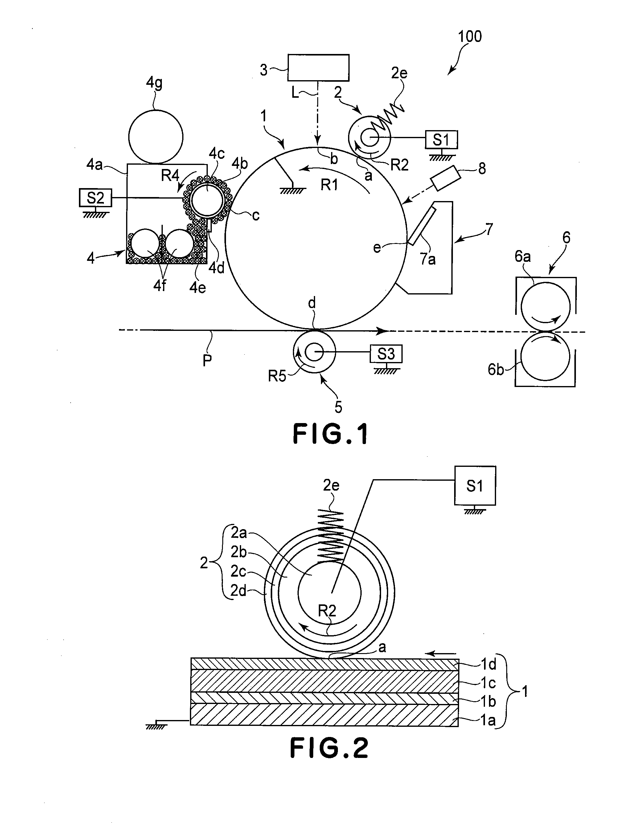
[0051]FIG. 1 is a schematic view for illustrating an example of a general structure of the image forming apparatus according to the present invention. In this embodiment, an image forming apparatus is a laser beam printer which utilizes a transfer type electrophotographic process, which employs a contact charging method and a reverse development method, and which has an A3 size as a maximum sheet passing size.

[0052]The image forming apparatus 100 includes a rotatable drum-type photosensitive member (electrophotographic photosensitive member) i.e., a photosensitive drum 1. The photosensitive drum 1 is rotationally driven in a direction indicated by an arrow R1 (counterclockwise direction). Around the photosensitive drum 1, along the rotational direction of the photosensitive drum 1, the following means are disposed. That is, the means include a charging device (a roller charger) 2 as a contact charging member which is a charging means, a...

embodiment 2

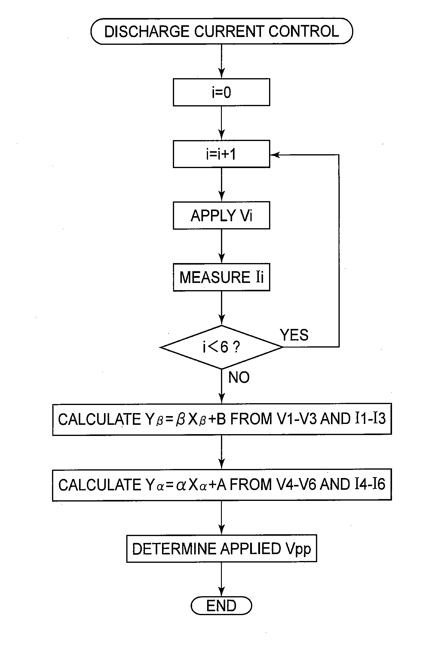
[0131]Another embodiment of the present invention will be described. In the image forming apparatus in this embodiment, members or portions having the same or corresponding functions and constitutions as those in the image forming apparatus described in Embodiment 1 and represented by the same reference numerals or symbols, thus being omitted from detailed description. In this embodiment, the constant current control of the charging voltage is carried out by using the value of the AC current flowing at the time when the AC voltage value determined by effecting the discharge current control described in Embodiment 1 is applied.

[0132]In the case where speed-up of the image forming apparatus is advanced to permit many times of an output operation, the electric resistance value of the charging roller fluctuations in a short time. When the constant voltage control was effected in such a case, it was found that the discharge current was excessively increased. On the other hand, in the cas...

embodiment 3

[0147]Another embodiment of the present invention will be described. In the image forming apparatus in this embodiment, members or portions having the same or corresponding functions and constitutions as those in the image forming apparatus described in Embodiment 1 and represented by the same reference numerals or symbols, thus being omitted from detailed description. In this embodiment, a method for reducing the time of the normal discharge current control described in Embodiments 1 and 2 will be described.

[0148]In Embodiment 1, in the normal discharge current control, first, in the setting of the process speed at 300 mm / sec and the charging frequency at 2 kHz, the sampling of 3 peak-to-peak voltages of less than Vth×2 (V) and 3 peak-to-peak voltages of not less than Vth×2 (V) was made. In addition thereto, in the setting of the process speed at 300 mm / sec and the charging frequency at 1 kHz, the sampling of 3 peak-to-peak voltages of less than Vth×2 (V) and 3 peak-to-peak voltage...


PUM


Abstract

An image forming apparatus includes a drum; a charging member; a charging bias applying device; an image forming device; a detecting device for detecting a current passing between the charging member and the drum; an executing device for selectively executing a first mode in which the charging bias of a first frequency is applied to form the image on the drum rotated at a first speed and a second mode in which the charging bias of a second frequency is applied to form the image on the drum rotated at a second speed; a calculating device for calculating information indicating a relationship between an output of the detecting device when the AC voltage of the first frequency is applied and an output of the detecting device when the AC voltage of the second frequency is applied; and an adjusting device for adjusting a peak-to-peak voltage to be applied to the charging member in the first mode based on the output of the detecting device obtained by applying the AC voltage of the first frequency to the charging member and for adjusting a peak-to-peak voltage to be applied to the charging member in the second mode based on the output of the detecting device obtained by applying the AC voltage of the first frequency to the charging member and the information calculated by the calculating device.

Description

FIELD OF THE INVENTION AND RELATED ART[0001]The present invention relates to an image forming apparatus for effecting discharge current amount control.[0002]In recent years, compared with a corona charging method, from the viewpoints of a low voltage process, a low ozone generation amount, and a low cost, a contact charging method in which a charging member of a roller type, a blade type, or the like is brought into contact with a surface of the image bearing member and then a voltage is applied to the charging member to electrically charge the surface of the image bearing member is going mainstream. Particularly, the roller type charging member is capable of effecting stable charging for a long term.[0003]The voltage applied to the charging member may be only a DC voltage but uniform charging can be realized by applying an oscillating voltage to alternately causing discharge on a positive side and on a negative side.[0004]For example, the oscillating voltage in the form of the DC v...

Claims


Application Information

Patent Timeline
Patent Type & Authority Applications(United States)
IPC IPC(8): G03G15/02
CPCG03G2215/025G03G15/0266
Inventor HANASHI, RYO
Owner CANON KK
Why Eureka
Try Eureka