Impeller

a centrifugal pump and impeller technology, applied in the field of centrifugal pump impellers, can solve the problems of reducing hydraulic efficiency, unacceptably noisy, and unstable flow transition from inside surface to outside or working side of the vane in the suction region, and achieve the effect of increasing hydraulic efficiency

Active Publication Date: 2010-09-23
GORMAN RUPP COMPANY
View PDF6 Cites 25 Cited by
  • Summary
  • Abstract
  • Description
  • Claims
  • Application Information

AI Technical Summary

Benefits of technology

[0004]The present invention provides a new and improved fluid pump which has increased hydraulic efficiency. In particular, the present invention provides a new and improved impeller for a fluid pump such as a centrifugal pump.

Problems solved by technology

It has been found that existing two and three vane impellers may operate at reduced efficiencies and / or can be unacceptably noisy especially when run at higher speeds in order to generate higher head pressures.
Due to this spacing, the flow transition from an inside surface of the vane to an outside or working side of the vane in the suction region is unstable, especially at flows to the right or left of the “best efficiency point” (BEP).
It is believed that these factors reduce the hydraulic efficiency and cause cavitation / noise.

Method used


Image

  • Impeller
  • Impeller
  • Impeller

Examples


Embodiment Construction

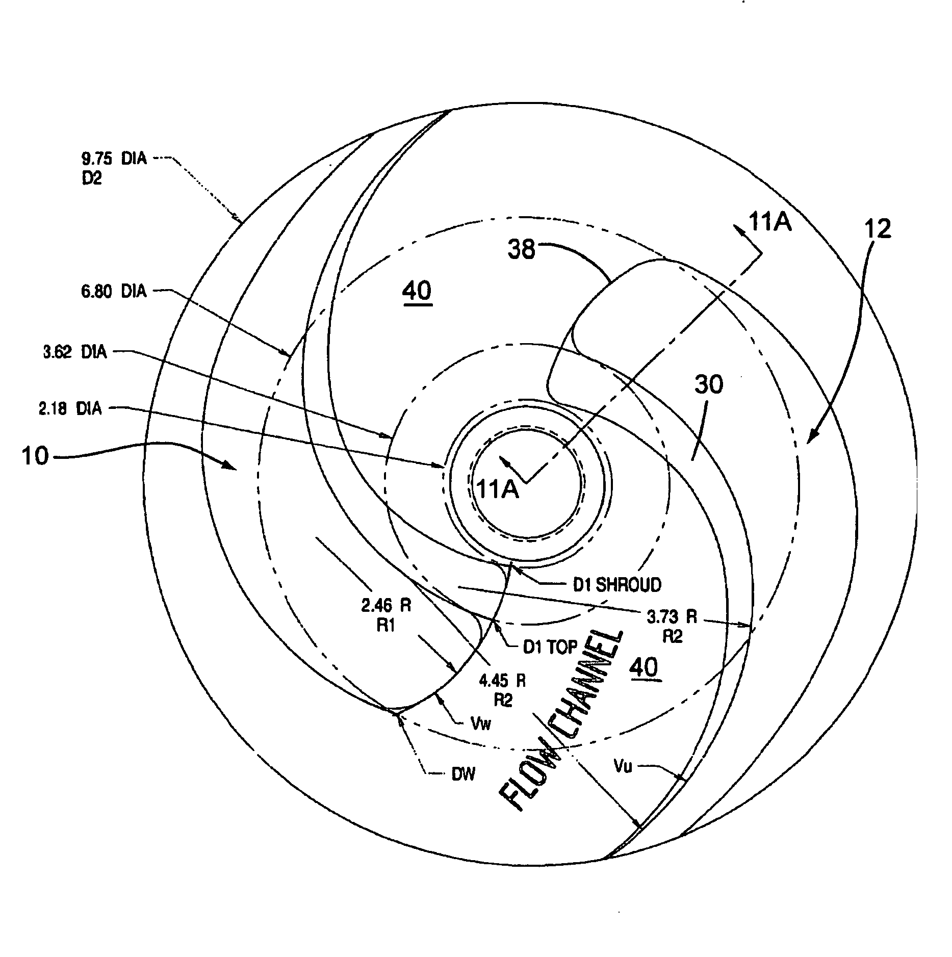
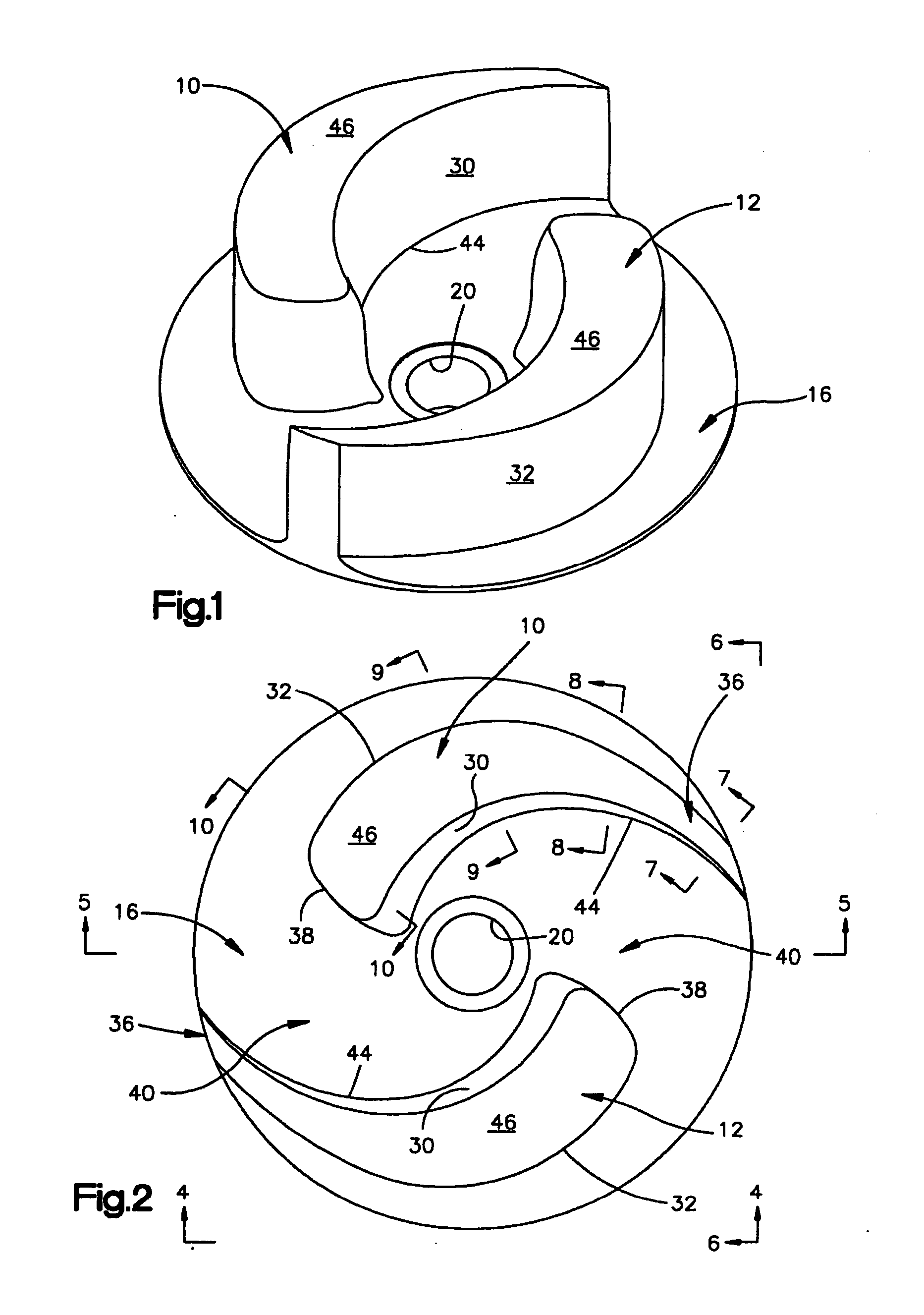
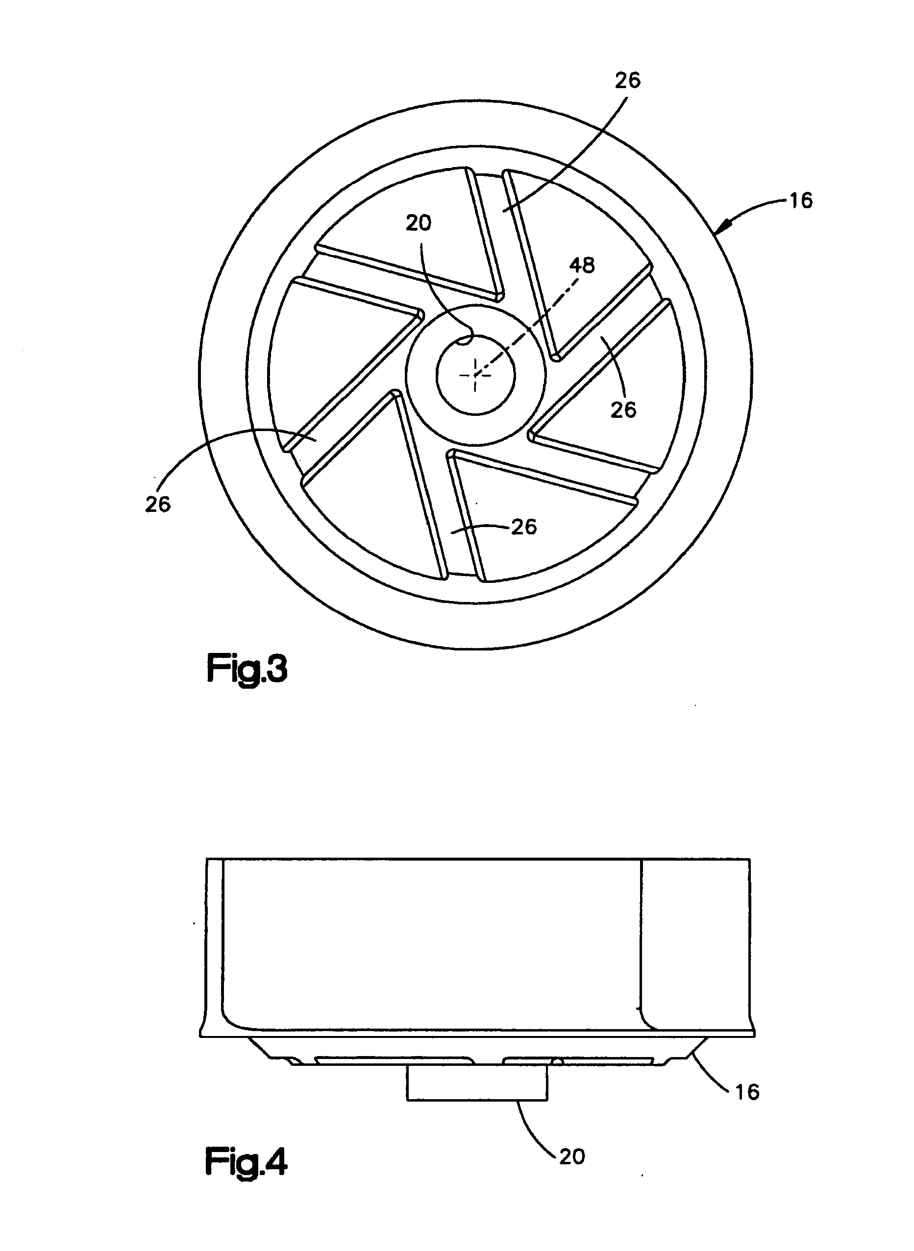
[0031]FIG. 1 illustrates the overall construction of an impeller embodying the present invention. The illustrated impeller includes two vanes 10, 12 which as viewed in FIG. 1, extend upwardly from a shroud 16. The shroud 16 defines a centrally positioned, threaded bore 20 by which the impeller is secured to a drive shaft (not shown). The drive shaft typically has a threaded end which is threadedly received by the bore 20. Other methods for attaching the impeller to the shaft such as keyways are also contemplated. The impeller typically rotates within an impeller chamber (not shown) which may be formed at least partially by a volute (not shown). Generally, the central portion of the impeller as viewed in FIG. 2 communicates with an inlet through which fluid i.e. water is drawn into the impeller chamber. The rotation of the impeller, in the counterclockwise direction, as viewed in FIG. 2 causes the water to be discharged, under pressure, to an outlet (not shown) which communicates wit...


PUM


Abstract

A pump impeller for a centrifugal pump The impeller is defined by a shroud rotatable about an axis of rotation At least two pump vanes extend axially from the shroud, each of the vanes configured as a blunted tear drop shape and having an inside wall and an outside wall, the leading edges of which are interconnected by a blunt wall The trailing edges of the inside and outside walls merge together A substantially constant width flow channel is defined between the blunted wall of one vane and a confronting surface defined by an inside wall of the other vane The vanes are tapered in the axial directions by inclining the inside wall of each vane radially outwardly.

Description

TECHNICAL FIELD[0001]The present invention relates generally to centrifugal pumps and in particular to a new and improved centrifugal pump impeller.BACKGROUND ART[0002]Centrifugal pumps often use multiple vane impellers to pump fluid such as water from an inlet to an outlet. Pump impellers are currently available which have two or more vanes. In order to pass solids through the pump, it is often desirable to utilize a two or three vane impeller. It has been found that existing two and three vane impellers may operate at reduced efficiencies and / or can be unacceptably noisy especially when run at higher speeds in order to generate higher head pressures.[0003]In the most recognized standard two vane impeller design for solids handling the two vanes are normally relatively perpendicular to the shroud. Each vane usually has a constant width of, for example 0.38 inch. In order to pass the required solids the distance between an inlet leading edge of one vane and a trailing edge at the O....

Claims


Application Information

Patent Timeline
Patent Type & Authority Applications(United States)
IPC IPC(8): F04D29/40F01D5/14
CPCF04D29/225F04D7/04Y10S416/02
Inventor SCOTT, THOMAS M.
Owner GORMAN RUPP COMPANY
Why Eureka
Try Eureka