
Composite alloy bonding wire and manufacturing method thereof

Active Publication Date: 2010-09-23
LEE JUN DER
View PDF2 Cites 27 Cited by
  • Summary
  • Abstract
  • Description
  • Claims
  • Application Information

AI Technical Summary

Benefits of technology

[0008]The subject of this invention is to provide a low cost composite alloy bonding wire made of Gold, silver and Palladium, capable of having performance as good as a pure Au bonding wire.
[0011]The composite alloy bonding wire is capable of having performance as good as a pure Au bonding wire and decreasing the manufacturing cost.

Problems solved by technology

However, pure Au bonding wire inevitably leads to high cost.

Method used


Image

  • Composite alloy bonding wire and manufacturing method thereof
  • Composite alloy bonding wire and manufacturing method thereof
  • Composite alloy bonding wire and manufacturing method thereof

Examples


embodiment 1

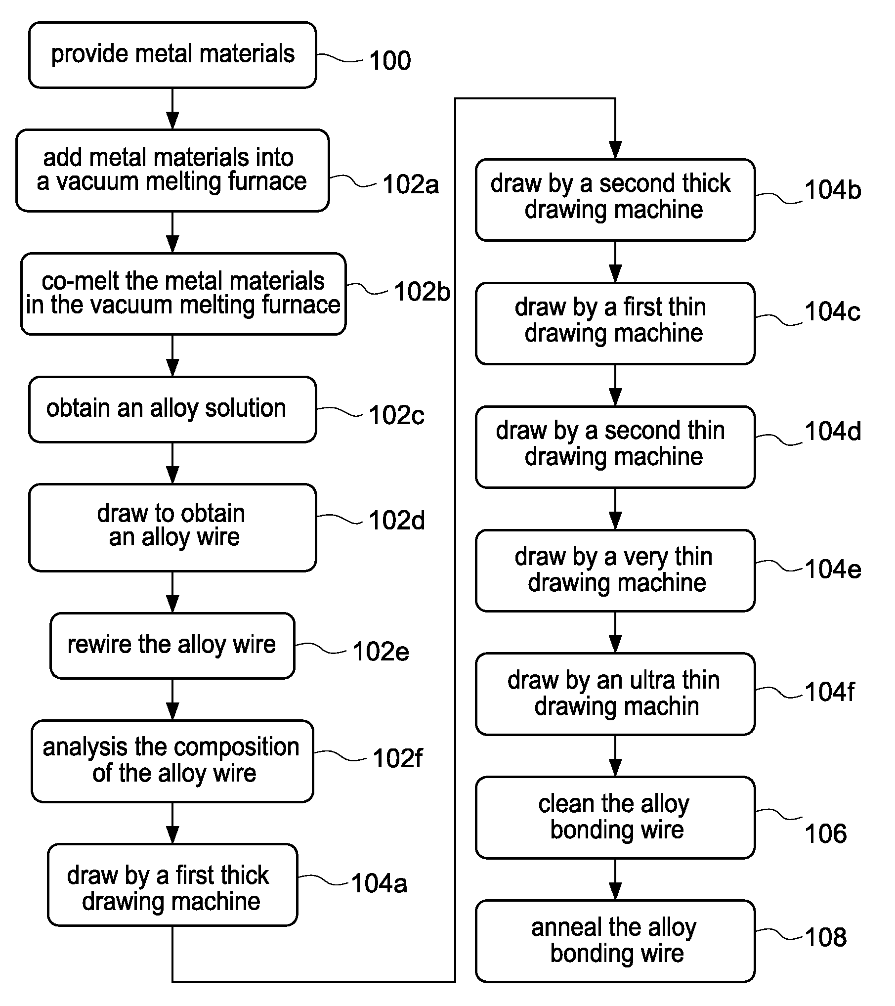
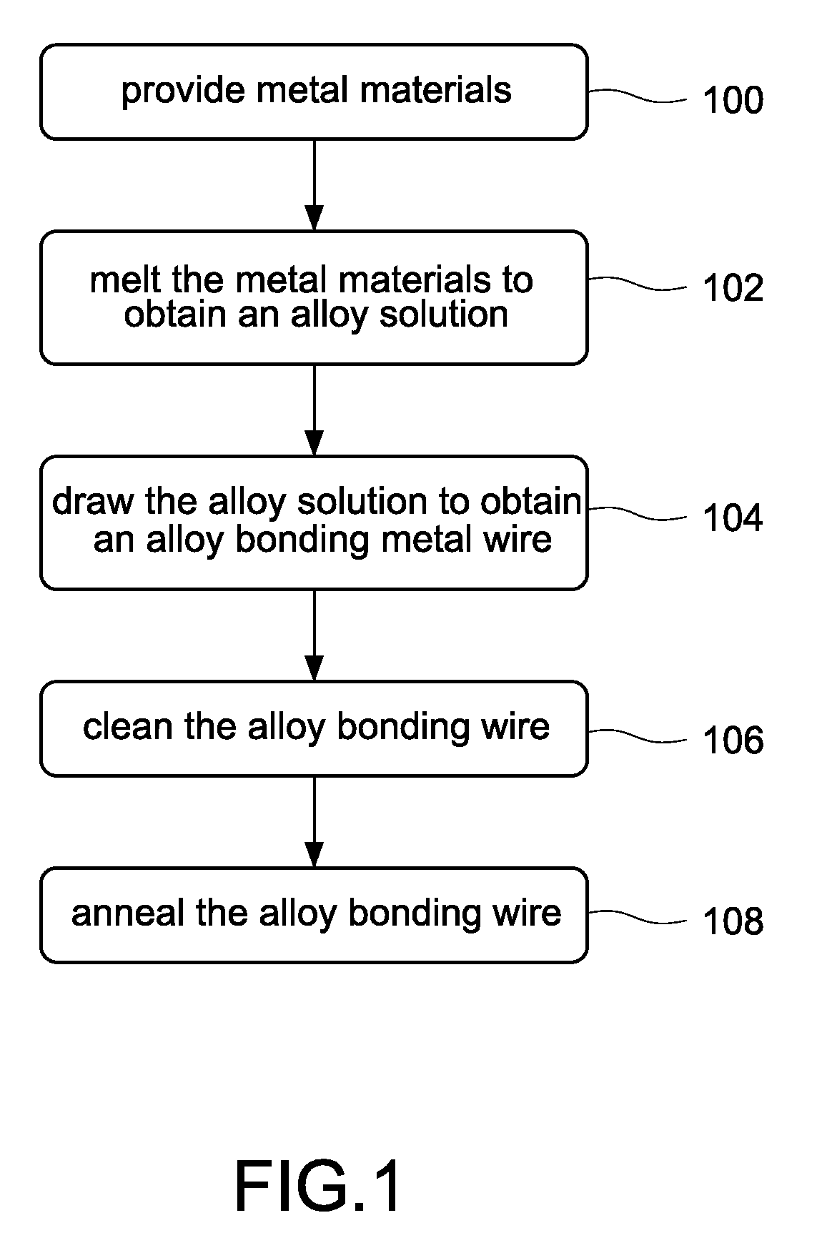
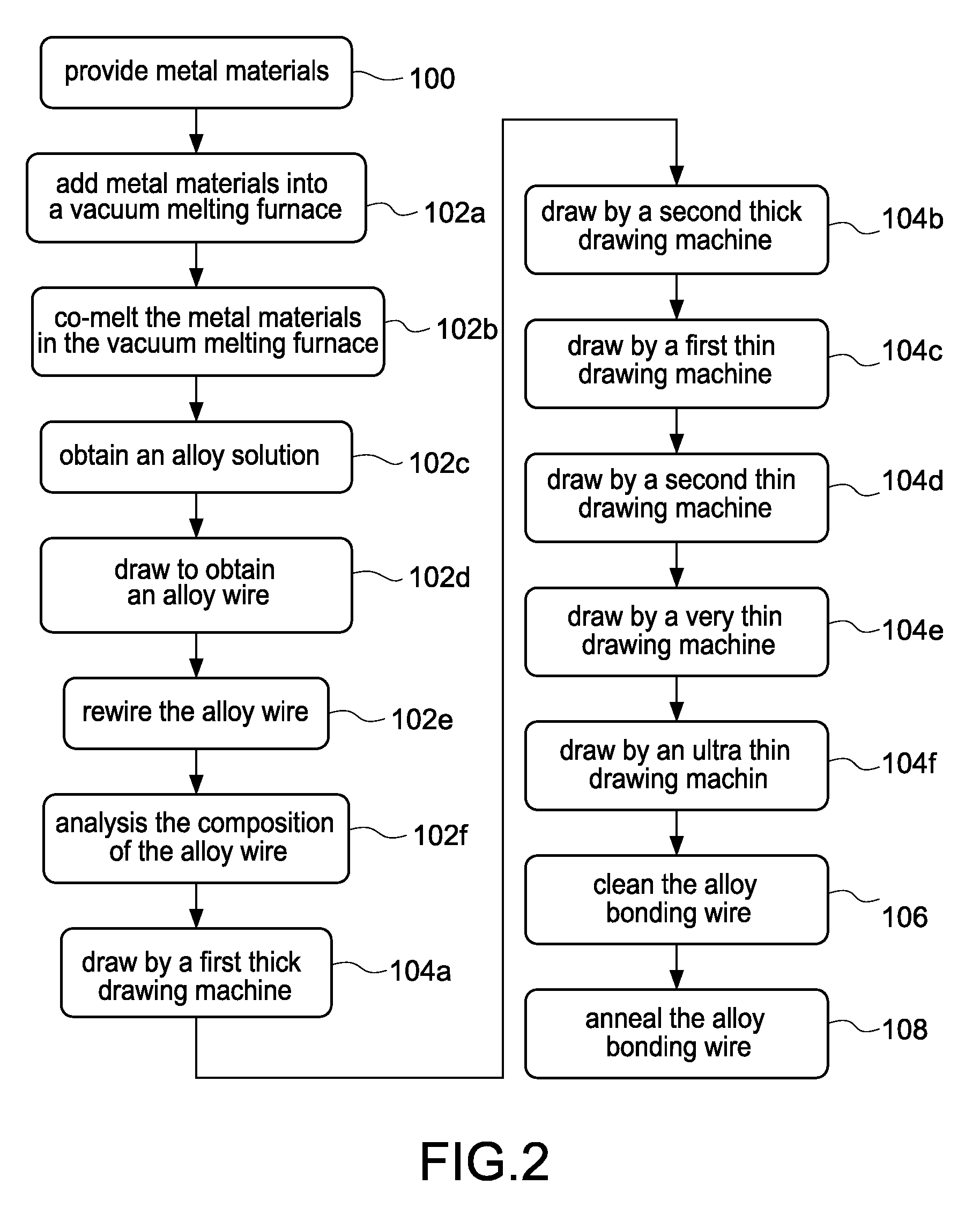
[0024]A primary material of Au and Ag is provided and is melted in a vacuum melting furnace. Then, specific amount of a secondary metal material of Pd is added into the vacuum melting furnace, and is co-melted with the primary material in the vacuum melting furnace to obtain a Au—Ag—Pd alloy solution. The Au—Ag—Pd alloy solution consists of: 30.00 wt. % Au, 66.00 wt. % Ag and 4.00 wt. % Pd.

[0025]Continuous casting and drawing processes are performed on the Au—Ag—Pd alloy solution to obtain a Au—Ag—Pd alloy wire with a diameter of 4 mm. The Au—Ag—Pd alloy wire is rewired by a reeling machine and then composition analysis is performed on the Au—Ag—Pd alloy wire to check if the obtained composition meets the requirement.

[0026]A drawing process is performed on the Au—Ag—Pd alloy wire; the obtained Au—Ag—Pd alloy wire with a diameter of 4 mm is drawn by a first thick drawing machine to obtain a Au—Ag—Pd alloy wire with a diameter of 3 mm. The Au—Ag—Pd alloy wire with a diameter of 3 mm i...

embodiment 2

[0028]A primary material of Au and Ag is provided and is melted in a vacuum melting furnace. Then, specific amount of a secondary metal material of Pd is added into the vacuum melting furnace, and is co-melted with the primary material in the vacuum melting furnace to obtain a Au—Ag—Pd alloy solution. The Au—Ag—Pd alloy solution consists of 8.00 wt. % Au, 86.00 wt. % Ag and 6.00 wt. % Pd.

[0029]Continuous casting and drawing processes are performed on the Au—Ag—Pd alloy solution to obtain a Au—Ag—Pd alloy wire with a diameter of 6 mm. The Au—Ag—Pd alloy wire is rewired by a reeling machine and then composition analysis is performed on the Au—Ag—Pd alloy wire to check if the obtained composition meets the requirement.

[0030]A drawing process is performed on the Au—Ag—Pd alloy wire; the obtained Au—Ag—Pd alloy wire with a diameter of 6 mm is drawn by a first thick drawing machine to obtain a Au—Ag—Pd alloy wire with a diameter of 3 mm. The Au—Ag—Pd alloy wire with a diameter of 3 mm is ...

embodiment 3

[0032]A primary material of Au and Ag is provided and is melted in a vacuum melting furnace. Then, specific amount of a secondary metal material of Pd is added into the vacuum melting furnace, and is co-melted with the primary material in the vacuum melting furnace to obtain a Au—Ag—Pd alloy solution. The Au—Ag—Pd alloy solution consists of 9.99 wt. % Au, 90.00 wt. % Ag and 0.01 wt. % Pd.

[0033]Continuous casting and drawing processes are performed on the Au—Ag—Pd solution to obtain a Au—Ag—Pd alloy wire with a diameter of 8 mm. The Au—Ag—Pd alloy wire is rewired by a reeling machine and then composition analysis is performed on the Au—Ag—Pd alloy wire to check if the obtained composition meets the requirement.

[0034]A drawing process is performed on the Au—Ag—Pd alloy wire; the obtained Au—Ag—Pd alloy wire with a diameter of 8 mm is drawn by a first thick drawing machine to obtain a Au—Ag—Pd alloy wire with a diameter of 2 mm. The Au—Ag—Pd alloy wire with a diameter of 2 mm is drawn ...


PUM

PropertyMeasurementUnit
Fractionaaaaaaaaaa
Fractionaaaaaaaaaa
Fractionaaaaaaaaaa

Abstract

A manufacturing method for a composite alloy bonding wire and products thereof. A primary material of Au and Ag is melted in a vacuum melting furnace, and then a secondary metal material of Pd is added into the vacuum melting furnace and is co-melted with the primary material to obtain a Au—Ag—Pd alloy solution. The obtained Au—Ag—Pd alloy solution is drawn to obtain a Au—Ag—Pd alloy wire. The Au—Ag—Pd alloy wire is then drawn to obtain a Au—Ag—Pd alloy bonding wire with a predetermined diameter.

Description

BACKGROUND OF THE INVENTION[0001]1. Field of the Invention[0002]The present invention generally relates to a bonding wire used as a packaging wire, in particular, to a bonding wire used in semiconductor packaging process.[0003]2. Description of Related Art[0004]In semiconductor device packaging processes for IC, LED, SAW, a wire bonding process is often performed to electrically connect the chip to the substrate by bonding wire, which used as a signal and electrical current transmitting medium between the chip and the substrate.[0005]The primary characteristics of a bonding wire, such as breaking load, elongation, loop, melting point, and bondability with IC chips are dependent on the materials used as the bonding wire. The performance of the packaged semiconductor device is influenced by the characteristics of the bonding wire. According to different types of chip and substrate, the adapted bonding wire has different specification.[0006]The conventional bonding wires are usually ma...

Claims


Application Information

Patent Timeline
IPC IPC(8): C22C5/06B21C1/02
CPCB21C1/003B21C37/047H01L2924/12041H01L2924/00014H01L2924/20755H01L2924/20754H01L2924/20753H01L2924/20752H01L2924/20751H01L2924/14H01L2924/01079H01L2924/01047H01L2924/01046H01L2924/01029H01L2924/01027H01L2924/01006H01L2924/01005H01L2224/45164H01L2224/45144H01L2224/45139H01L2224/45015H01L2224/43H01L24/45H01L24/43C22F1/14C22C5/06B23K35/0261B23K35/24B23K35/3006C22C1/02H01L2924/00011H01L2924/013H01L2924/00H01L2224/48H01L2224/43848H01L2924/01049
Inventor LEE, JUN-DER
Owner LEE JUN DER
Learn More