

Method and system of dry processing of converter slag in copper smelting
a technology of dry processing and converter slag, which is applied in the field of dry processing of slag discharged from a converter in copper smelting, can solve the problems of not being recommended for the use as a raw material for iron, difficulty in finding firms receiving, and high contents of copper and zinc to achieve the effect of reducing the difficulty of finding firms receiving
Inactive Publication Date: 2010-09-30
PAN PACIFIC COPPER CO LTD
View PDF3 Cites 17 Cited by
- Summary
- Abstract
- Description
- Claims
- Application Information
AI Technical Summary
Benefits of technology
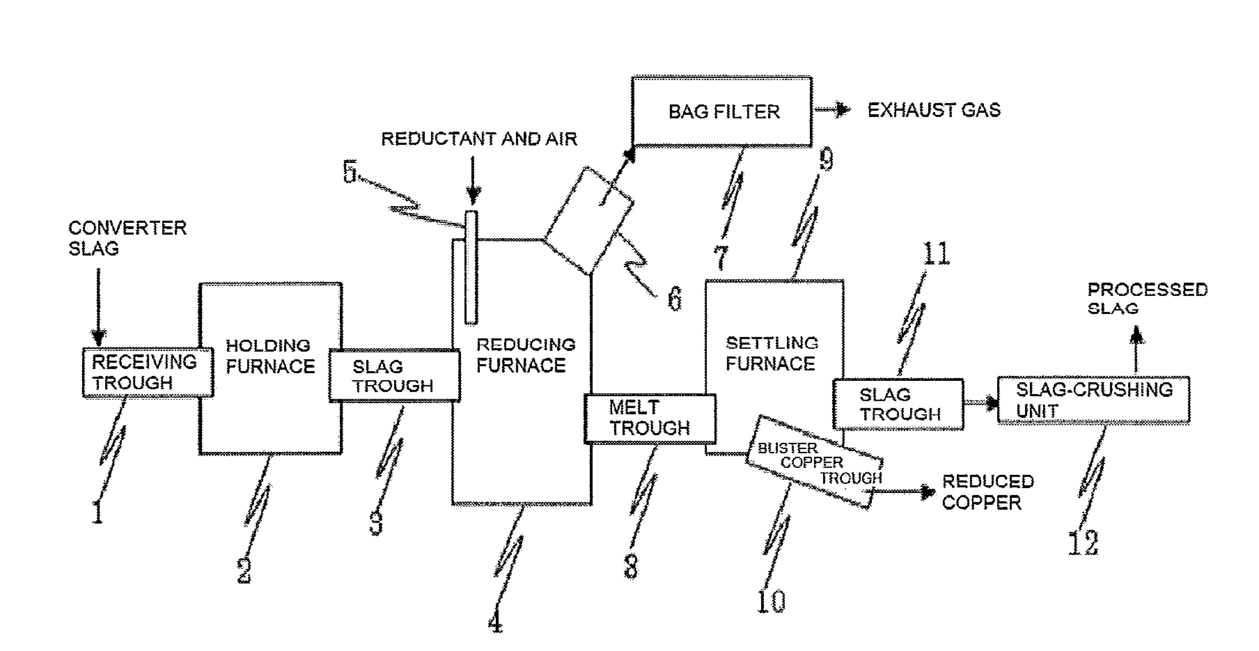
[0010]Through extensive research for solving the problem, the present inventors have discovered a method for processing slag to remove zinc through volatilization from the slag and to reduce copper oxide in a reducing furnace by a slag-fuming process used widely in zinc smelting and, subsequently, to separate the reduced blister copper from the slag by sedimentation in the reducing furnace or in a settling furnace arranged in series with the reducing furnace after the slag is transferred thereto. According to the present method, the copper and zinc contents in the converter slag can be reduced to levels suitable for use as a raw material for iron making. Also, the converter slag can be continuously processed through the sedimentation separation in the settling furnace as a separate process, not in the reducing furnace.
[0012]Although a slag-fuming process is commonly used in processing slag in zinc smelting, it has not been conventionally applied to processing of converter slag in copper smelting explained in the present invention and not been required either. The feature of the present invention is, therefore, that a slag-fuming process is applied to processing of converter slag in copper smelting. Alternatively, in an embodiment, drained slag from a reducing furnace is transferred to a settling furnace and the reduced copper is separated by sedimentation and recovered there. In this case, continuous processing of converter slag is possible, which is very favorable to actual operation.
[0013]Accordingly, an aspect of the present invention provides a method for processing converter slag produced in copper smelting, encompassing feeding converter slag into a reducing furnace, reducing zinc and copper contained in the converter slag by heating and removing the reduced zinc through volatilization in the reducing furnace.
[0018]In a further embodiment of the present invention, the method further encompassing feeding the converter slag from a holding furnace into the reducing furnace, wherein the holding furnace retains the converter slag in a molten state and controls the feed rate of the converter slag to the reducing furnace.
Problems solved by technology
A new route for recycling converter slag is required, since the recent shrinking trend in the cement industry in Japan has created difficulty in finding firms receiving the iron concentrate produced through a slag beneficiation process, as described in Nonpatent Document 1.
However, since the converter slag contains about 4% by mass of copper and about 2% by mass of zinc, the contents of copper and zinc are too high to use the slag as a raw material for iron making.
However, since converter slag processed by a method described in Nonpatent Document 2 or 3 also has high copper and zinc contents for use as a raw material for iron making, it may not be recommended for the use as a raw material for iron making.
Method used
View moreImage
Smart ImageViewing Examples


Examples
examples
[0046]Examples of the present invention are described below. The examples are merely illustrative, and not limiting the invention.
Login to View More PUM
| Property | Measurement | Unit |
|---|---|---|
| flow rate | aaaaa | aaaaa |
| feed rate | aaaaa | aaaaa |
| purity | aaaaa | aaaaa |
Abstract
A method for processing converter slag produced in copper smelting includes feeding the converter slag into a reducing furnace, reducing zinc and copper contained in the converter slag by heating and removing the reduced zinc through volatilization in a reducing furnace. The slag discharged from the converter is transformed into a raw material for iron making.
Description
BACKGROUND OF THE INVENTION[0001]1. Field of the Invention[0002]The present invention relates to a method and a system of dry processing of slag discharged from a converter in copper smelting, and in particular, to a method and a system of dry processing of slag discharged from a converter in copper smelting, for transforming the slag into a raw material for iron making.[0003]2. Description of the Related Art[0004]A general process of copper smelting is outlined below. Raw material copper concentrate is oxidized in a flash furnace to form matte having a copper content of about 68% and flash furnace slag composed largely of iron oxide and silicic acid. The matte and the slag are separated. The matte is fed into a converter to form blister copper having a copper content of about 99% and converter slag composed primarily of iron oxide silicates. The copper and the slag are separated. The blister copper is cast into an anode having a higher copper purity. The anode is electrolytically-r...
Claims
Login to View More Application Information
Patent Timeline
 Patent Type & AuthorityApplications(United States)
IPC IPC(8): C22B15/06C22B19/00C22B9/00C21B7/14C22B1/14C22B1/00
CPCC22B5/12C22B15/0054C22B7/04Y02P10/20
InventorSASAKI, TAKAFUMIFUJII, TAKAYOSHI
OwnerPAN PACIFIC COPPER CO LTD