Control apparatus for an internal combustion engine

Active Publication Date: 2010-09-30
MITSUBISHI ELECTRIC CORP
View PDF8 Cites 18 Cited by
  • Summary
  • Abstract
  • Description
  • Claims
  • Application Information

AI Technical Summary

Benefits of technology

[0023]According to the present invention, when fueling is performed again during concentration change of a single composition after fueling, the concentration estimation period for the single composition or a start determination period for the concentration change of the single com

Problems solved by technology

There occurs a delivery delay before fuel in a fuel tank which has the alcohol concentration changed due to refueling arrives at an injector that supplies the fuel to an internal combustion engine, and the delay becomes larger in a returnless fuel supply system.
On the downstream side of the pressure regulator, the fuel moves only by a distance equivalent to the amount of the fuel injected from the injector and a delay in alcohol concentration change is large.
However, on the upstream side of the pressure regulator, because the fuel always circulates through a channel of from the fuel tank to the fuel pump to the pressure regulator to the fuel tank, the delay in alcohol concentration change is extremely small.
A delay in a relatively slim fuel supply pipe is

Method used


Image

  • Control apparatus for an internal combustion engine
  • Control apparatus for an internal combustion engine
  • Control apparatus for an internal combustion engine

Examples


first embodiment

[0048]In a first embodiment of the present invention, a concentration change period is set after fueling determination and alcohol concentration in fuel is estimated as single composition concentration in fuel based on an air-fuel ratio feedback correction coefficient.

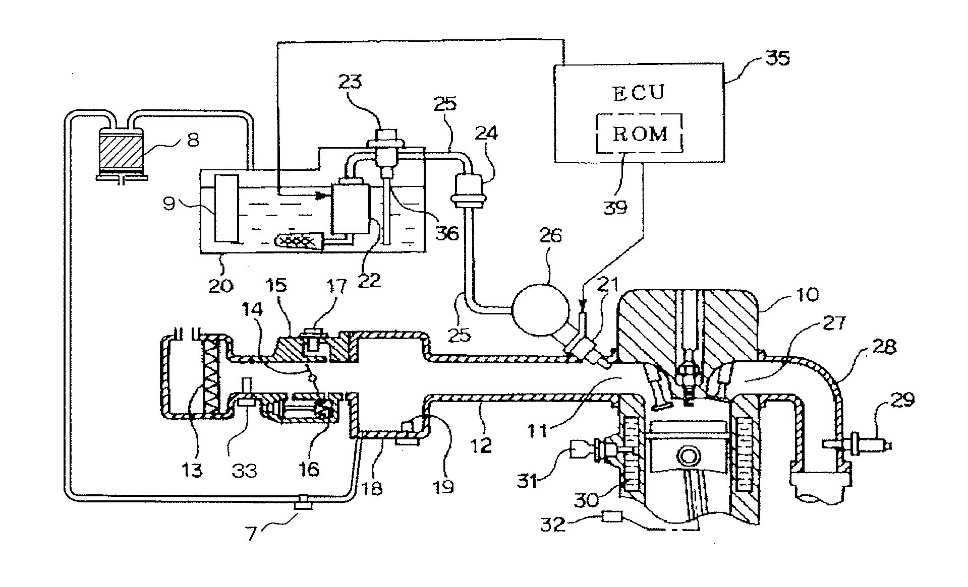
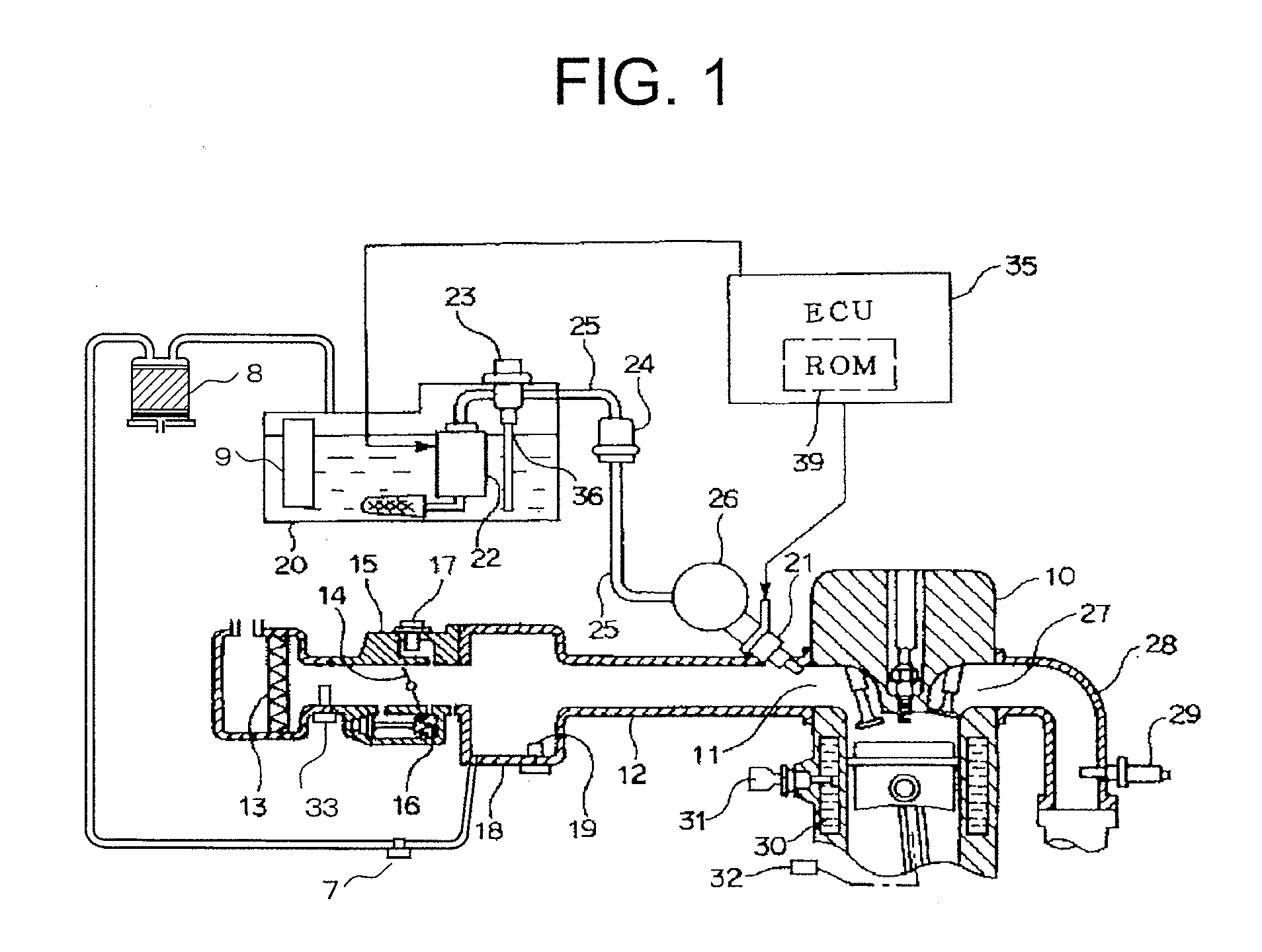
[0049]FIG. 1 illustrates a schematic configuration of a control apparatus for an internal combustion engine according to the first embodiment of the present invention. It should be noted that the internal combustion engine illustrated in FIG. 1 is a kind of internal combustion engine that uses a fuel containing alcohol. An air cleaner 13 is arranged at a most upstream portion of an intake pipe 12 which is connected to individual intake ports 11 of an engine 10 that constitutes the internal combustion engine. An air flow meter 33 for detecting an intake air amount qa of air to the engine 10 is mounted at a location downstream of the air cleaner 13. Further, a throttle valve 14 is arranged at a location downstream of the...

second embodiment

[0126]In a second embodiment of the present invention, alcohol concentration estimation is started when fluctuation in air-fuel ratio feedback correction coefficient increases after fueling. In the second embodiment, only the calculation routine for alcohol concentration estimation illustrated in FIGS. 5 and 6 is changed from that of the first embodiment, and hence description the same as the description of the first embodiment except the description of FIGS. 5 and 6 is omitted.

[0127]FIGS. 11 to 13 illustrate a calculation routine for alcohol concentration estimation according to the second embodiment replacing FIGS. 5 and 6 in the first embodiment. The calculation routine is executed at every predetermined time interval, for example, 5 ms.

[0128]In FIG. 11, first, in Step 1301, it is determined whether fuel is supplied to the fuel tank 20 in the same manner as Step 801 in the first embodiment.

[0129]When it is determined in Step 1302 that the fueling is not in a concentration change ...


PUM


Abstract

Provided is a control apparatus for an internal combustion engine which is capable of estimating a single composition concentration based on an air-fuel ratio correction amount obtained by using an output of an air-fuel ratio sensor in exhaust gas and optimizing a fuel injection amount by using a concentration estimation value. When fueling is performed again during alcohol concentration change after the fueling, an alcohol concentration estimation period or a start determination period for the alcohol concentration change is extended by an integrated fuel injection amount from initial fueling until refueling, whereby alcohol concentration estimation accuracy is improved with respect to the alcohol concentration change due to the initial fueling and the refueling.

Description

BACKGROUND OF THE INVENTION[0001]1. Field of the Invention[0002]The present invention relates to a control apparatus for an internal combustion engine which enables a motor vehicle to travel even with mixed fuel having an arbitrary ratio of alcohol (single composition) and gasoline, and in particular, to a technique of estimating a single composition concentration based on an air-fuel ratio correction amount obtained by using an output of an air-fuel ratio sensor in exhaust gas and optimizing a fuel injection amount by using a concentration estimation value.[0003]2. Description of the Related Art[0004]There is a motor vehicle called a flexible fuel vehicle (FFV) which is capable of traveling with mixed fuel of various compositions of alcohol and gasoline, in addition to with gasoline alone.[0005]Alcohol has a C (carbon) atom content different from that of ordinary gasoline, and hence, when mixed fuel of alcohol and gasoline is supplied to an internal combustion engine used for the F...

Claims


Application Information

Patent Timeline
IPC IPC(8): F02D41/00F02D41/30
CPCF02D41/0025F02D19/088F02D41/1454F02D41/1488F02D41/2441F02D41/2448F02D41/2454F02D41/2474F02D2041/1409F02D2200/0612F02D2200/0616F02M25/089Y02T10/36F02D19/061F02D19/0665F02D19/084F02D41/0032Y02T10/30
Inventor TAKUBO, HIDEKI
Owner MITSUBISHI ELECTRIC CORP
Why Eureka
Try Eureka