Disc brake apparatus

a disc brake and disc technology, applied in the direction of axially engaging brakes, actuators, braking elements, etc., can solve the problems of inability to easily engage with the end surface, unstable behavior so as to reduce the roll moment of the brake pad, reduce processing costs, and suppress the generation of brake noise

Inactive Publication Date: 2010-09-30
ADVICS CO LTD
View PDF12 Cites 12 Cited by
  • Summary
  • Abstract
  • Description
  • Claims
  • Application Information

AI Technical Summary

Benefits of technology

[0009]In the disc brake apparatus according to the present invention, at the time of braking the disc rotor, torque at the time of braking is receivable at three points in total including two engagement points between the V-shape inner peripheral abutments of the brake pads and the inner periphery support shafts, and one engagement point between the outer peripheral abutments of the brake pads and the outer periphery support shafts. Therefore, behavior of the brake pads is stabilized in comparison to a case where the torque at the time of braking is received on an unstable flat surface (for example, in a case of the disc brake apparatus described in Patent Literature 1). Thus, it is possible to suppress generation of brake noise in accordance with unstable behavior at the time of braking. Areas (processing areas) of the points where the torque at the time of braking is received are reduced in comparison to a case where the torque at the time of braking is received on an unstable flat surface. Thus, it is possible to reduce processing cost.
[0010]In the disc brake apparatus according to the present invention, the points where the torque at the time of braking is received include the positions on the inner side of the linings in the rotor radial direction and on the center in the rotor circumferential direction, and also the positions on the outer side of the linings in the rotor radial direction and on the middle in the rotor circumferential direction. These positions are not largely away from end surfaces of the linings in the rotor circumferential direction (the moment arm is short). Thus, it is possible to reduce the roll moment of the brake pads generated at the time of braking in comparison to the disc brake apparatus described in Patent Literature 1, and also to obtain uniform surface pressure distribution of the linings relative to the disc rotor so as to suppress uneven abrasion of the linings in the rotor circumferential direction.
[0011]In the present invention, the bias member may have the bias force set so that leading parts of the brake pads are on the outer side of trailing parts of the brake pads in the rotor radial direction. In this case, the three points where the torque at the time of braking is received are in an already engaged (abutted) state by the bias force of the bias member before braking. Thus, it is possible to suppress a chattering of the brake pads on the support shafts connected to the caliper at the time of non-braking of the disc rotor. At the time of braking, the back plates of the brake pads are not abutted with the outer periphery support shafts. Thus, it is possible to suppress (eliminate) generation of a clonk (an impact sound generated by abutment of the back plates with the outer periphery support shafts).

Problems solved by technology

The abutment (the flat surface) is an unstable flat surface which is easily changed due to an engagement relationship between the inner peripheral engagement surfaces of the back plates and the inner periphery support shafts (manufacturing errors of the members, connection errors or deformation caused by thermal expansion) or the like, and which is not easily engaged with the end surfaces (the flat surfaces) of the back plates while being flush with the end surfaces.
Therefore, there is a fear that behavior of the brake pads may be unstable at the time of braking and hence brake noise may be generated.
Thus, an area requiring the processing work is large and hence the cost is increased.
Thus, surface pressure distribution of the linings relative to the disc rotor is insufficient, and uneven abrasion of the linings in the rotor circumferential direction is unavoidable.

Method used


Image

  • Disc brake apparatus
  • Disc brake apparatus
  • Disc brake apparatus

Examples


first embodiment

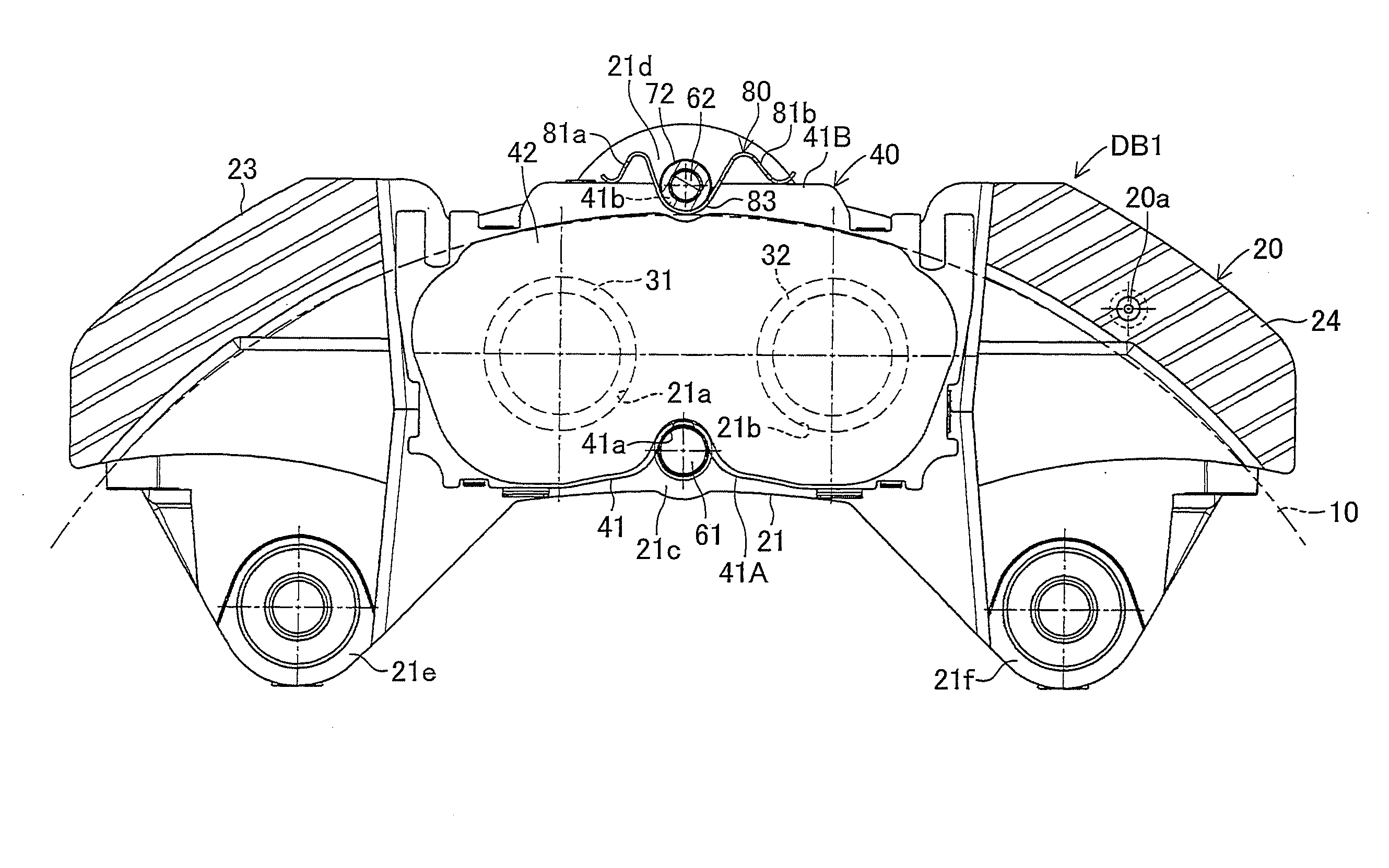
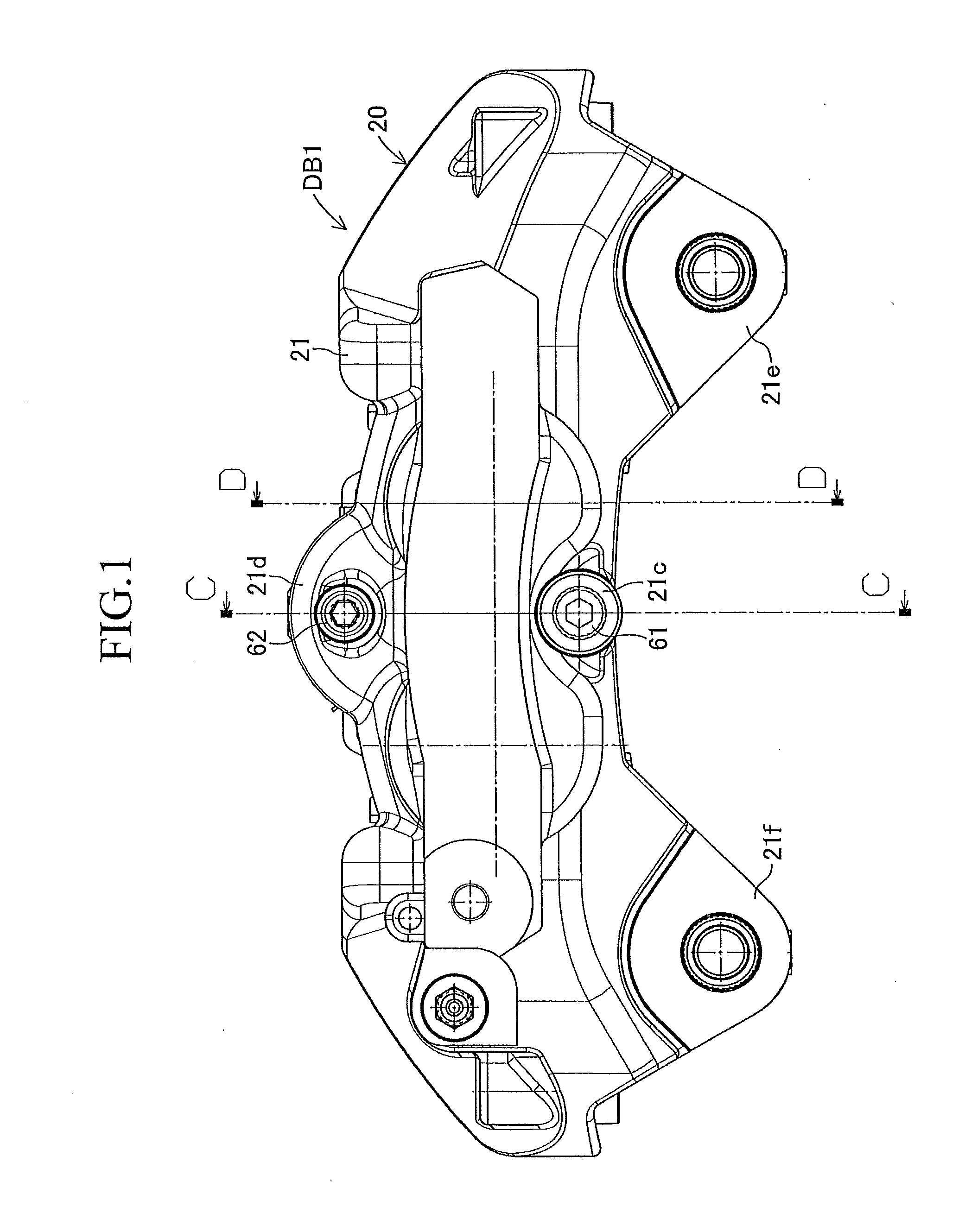
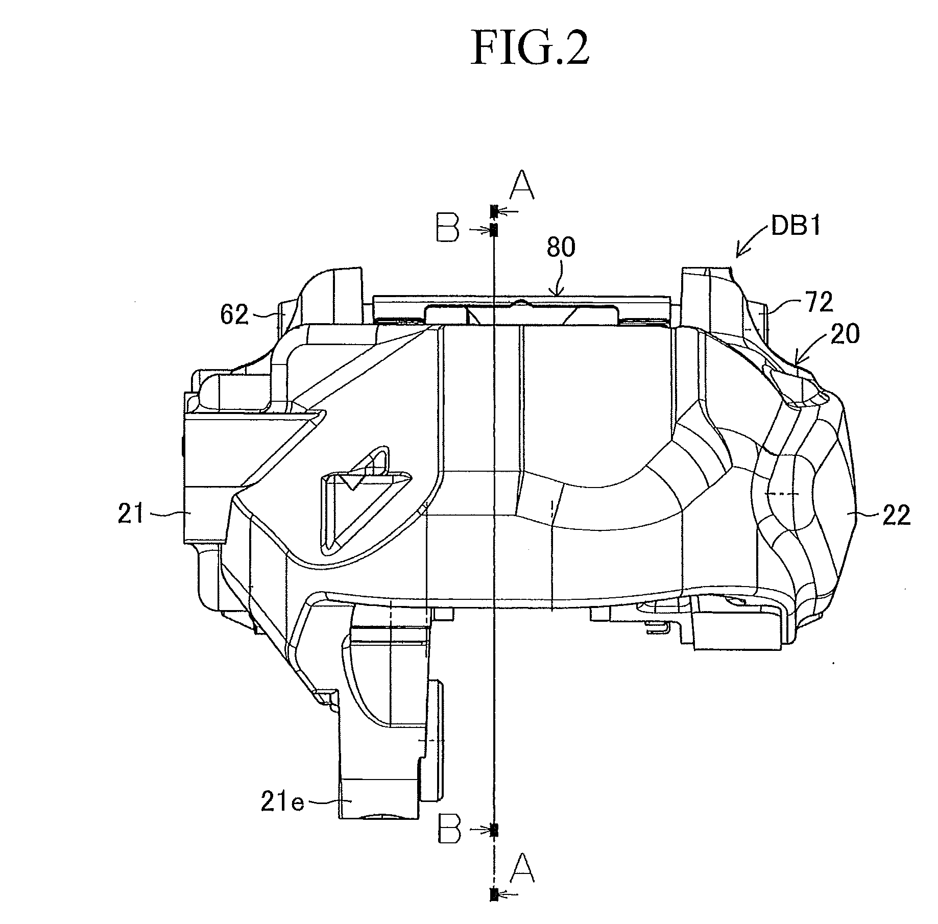
[0024]FIGS. 1 to 6 show a first embodiment in which a disc brake apparatus of the present invention is utilized as an opposed piston type (fixed type) disc brake apparatus for a vehicle. A disc brake apparatus DB1 according to the first embodiment is provided with a disc rotor 10 connected to an axle hub (a rotating member not shown in the figures) and rotated integrally with a wheel (not shown), a caliper 20 arranged so as to be astride a part of an outer peripheral portion of this disc rotor 10, four pistons 31, 32, 33, 34 connected to this caliper 20, an inner-side brake pad 40, and an outer-side brake pad 50. The disc brake apparatus DB1 is also provided with, in the caliper 20, an inner-side inner periphery support shaft 61, an inner-side outer periphery support shaft 62, an outer-side inner periphery support shaft 71, an outer-side outer periphery support shaft 72, and a plate spring 80.

[0025]As shown in FIG. 5, the disc rotor 10 has circular brake surfaces 10a, 10b to be grip...

second embodiment

[0046]FIGS. 7 to 10 show a second embodiment in which a disc brake apparatus of the present invention is utilized as an opposed piston type (fixed type) disc brake apparatus for a vehicle. A disc brake apparatus DB2 according to the second embodiment is provided with a disc rotor 110 connected to an axle hub (a rotating member not shown in the figures) and rotated integrally with a wheel (not shown), a caliper 120 arranged so as to be astride a part of an outer peripheral portion of this disc rotor 110, four pistons 131, 132, 133, 134 connected to this caliper 120, an inner-side brake pad 140, and an outer-side brake pad 150. The disc brake apparatus DB2 is also provided with an inner-side inner periphery support shaft 161, a pair of inner-side outer periphery support shafts 162, 162, an outer-side inner periphery support shaft 171, a pair of outer-side outer periphery support shafts 172, 172, and a plate spring 180.

[0047]According to the second embodiment, a pair of the inner-side ...

second embodiments

Modification of First and Second Embodiments

[0051]According to the first and second embodiments described above, the plate spring (80, 180) biases the inner-side brake pad (40, 140) and the outer-side brake pad (50, 150) inward in the rotor radial direction so that the leading parts of the brake pads are on the outer side of the trailing parts of the brake pads in the rotor radial direction. However, the type of the bias member is not limited to the plate spring but the bias member may be properly modified to a rod spring, for example.

[0052]According to the embodiments described above, the inner-side outer periphery support shaft (62, 162) and the outer-side outer periphery support shaft (72, 172) are integrally coupled to each other by screwing. However, these shafts may be separately provided.

[0053]According to the embodiments described above, the caliper 20, 120 is provided with the inner housing portion 21, 121 and the outer housing portion 22, 122 facing each other across part ...


PUM


Abstract

The present invention is to stabilize behavior of brake pads at the time of braking of a disc brake so as to suppress generation of brake noise, and also to reduce the roll moment of the brake pads generated at the time of braking so as to suppress uneven abrasion of linings. A back plate (41) of a brake pad (40) is biased inward in the rotor radial direction by a plate spring (80). The back plate (41) is engaged at two points with an inner periphery support shaft (61) provided integrally with a caliper (20) on a V-shape inner peripheral abutment (41a) (provided in the back plate (41) on the inner side of a lining (42) in the rotor radial direction and on the center in the rotor circumferential direction), and engaged at one point with an outer periphery support shaft (62) provided integrally with the caliper (20) on an outer peripheral abutment (41b) (provided in the back plate (41) on the outer side of the lining (42) in the rotor radial direction and on the center in the rotor circumferential direction).

Description

BACKGROUND OF THE INVENTION[0001]1. Field of the Invention[0002]The present invention relates to a disc brake apparatus, particularly a disc brake apparatus provided with a disc rotor connected to a rotating member (such as an axle hub) and rotated integrally with the rotating member, a caliper connected to a support member (such as a vehicle body) so as to be astride a part of an outer periphery of this disc rotor, a pair of brake pads arranged so as to grip the disc rotor and supported on the caliper by support shafts movably in the rotor axial direction, and pistons connected to the caliper for pressing the brake pads toward the disc rotor, the pistons being adapted to press back plates of the brake pads so that linings of the brake pads are slidably forced against brake surfaces of the disc rotor for braking the disc rotor.[0003]2. Description of Related Art[0004]This type of disc brake apparatus is described in National Patent Publication No. 2008-527272 (will be referred to as...

Claims


Application Information

Patent Timeline
Patent Type & Authority Applications(United States)
IPC IPC(8): F16D65/16
CPCF16D55/228F16D65/095F16D2121/02F16D2055/007F16D2055/0091F16D65/0977
Inventor MORITA, SHINICHIITSUAKI, SATORU
Owner ADVICS CO LTD
Why Eureka
Try Eureka