Selective soldering apparatus with jet wave solder jet and nitrogen preheat
a soldering apparatus and jet wave technology, applied in the direction of soldering auxiliaries, soldering media, soldering feeding devices, etc., can solve the problems of large x-y-z handling mechanism, inability to fit sideways between the components, and inability to provide a x-y-z handling mechanism for the board, so as to reduce the thermal shock and control the heating rate of the board
- Summary
- Abstract
- Description
- Claims
- Application Information
AI Technical Summary
Benefits of technology
Problems solved by technology
Method used
Image
Examples
first embodiment
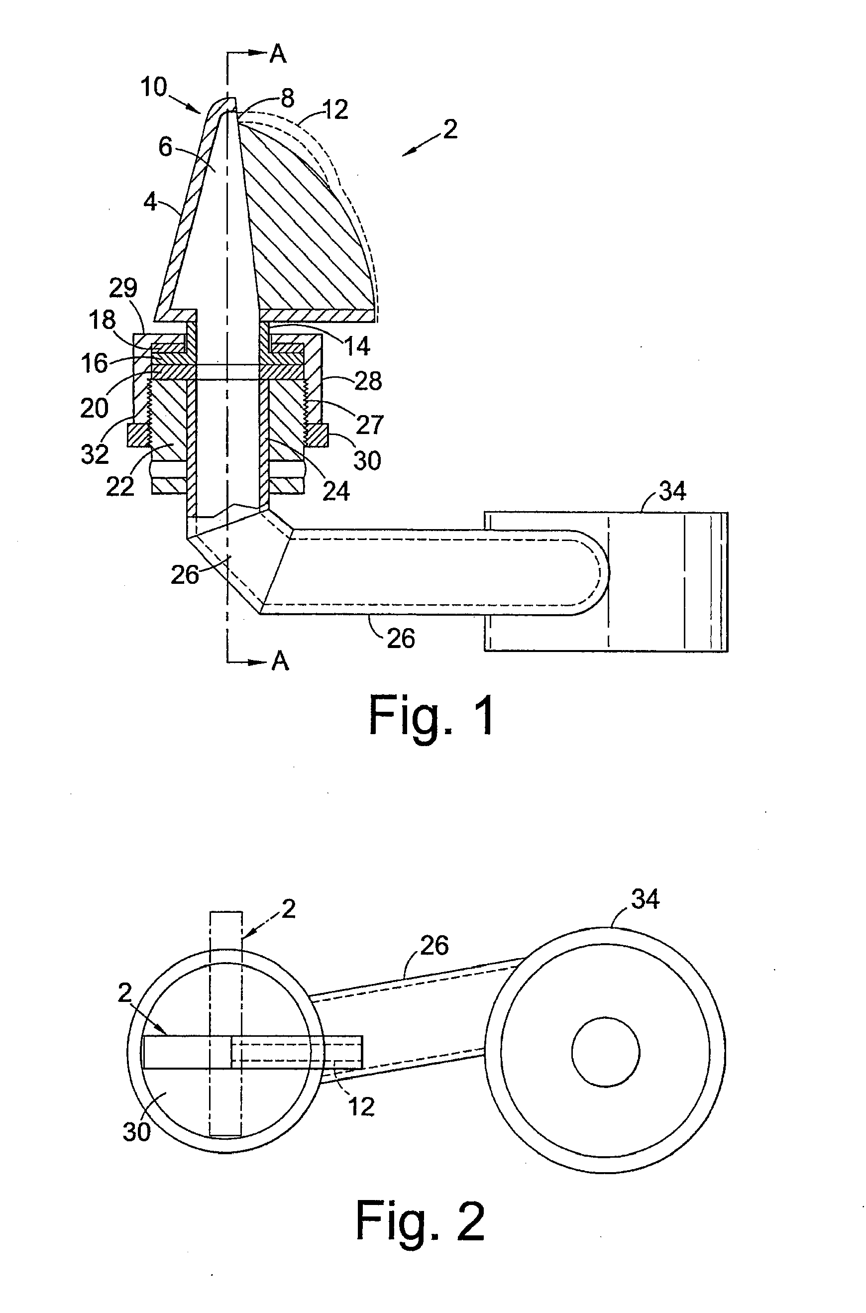
[0036]FIG. 1 shows in cross-section a rotatable solder nozzle 2 of the invention. The nozzle 2 has an upper body 4 defining a chamber 6 having an outlet 8 at an upper end 10. In use, molten solder is pumped through chamber 6 to exit outlet 8 in the manner of a stream or jet 12, illustrated in dotted outline in FIG. 1. Leads or other component parts to be soldered are passed through the solder jet. This may be achieved by moving the leads through the solder jet with the nozzle stationary, or, as in our preferred embodiment, by moving the jet, across the leads by moving the nozzle underneath a stationary board.
[0037]As seen from FIG. 2, the body 4 is generally elongate in one direction. Body 4 is mounted to be rotatable about an axis A-A. Body 4 has a cylindrical portion 14 centred on axis A-A and ending in a laterally extending circular flange 16. Flange 16 is mounted between two slip washers 18, 20. Washer 18, 20 may be formed from a suitable bearing material. The bearing material d...
second embodiment
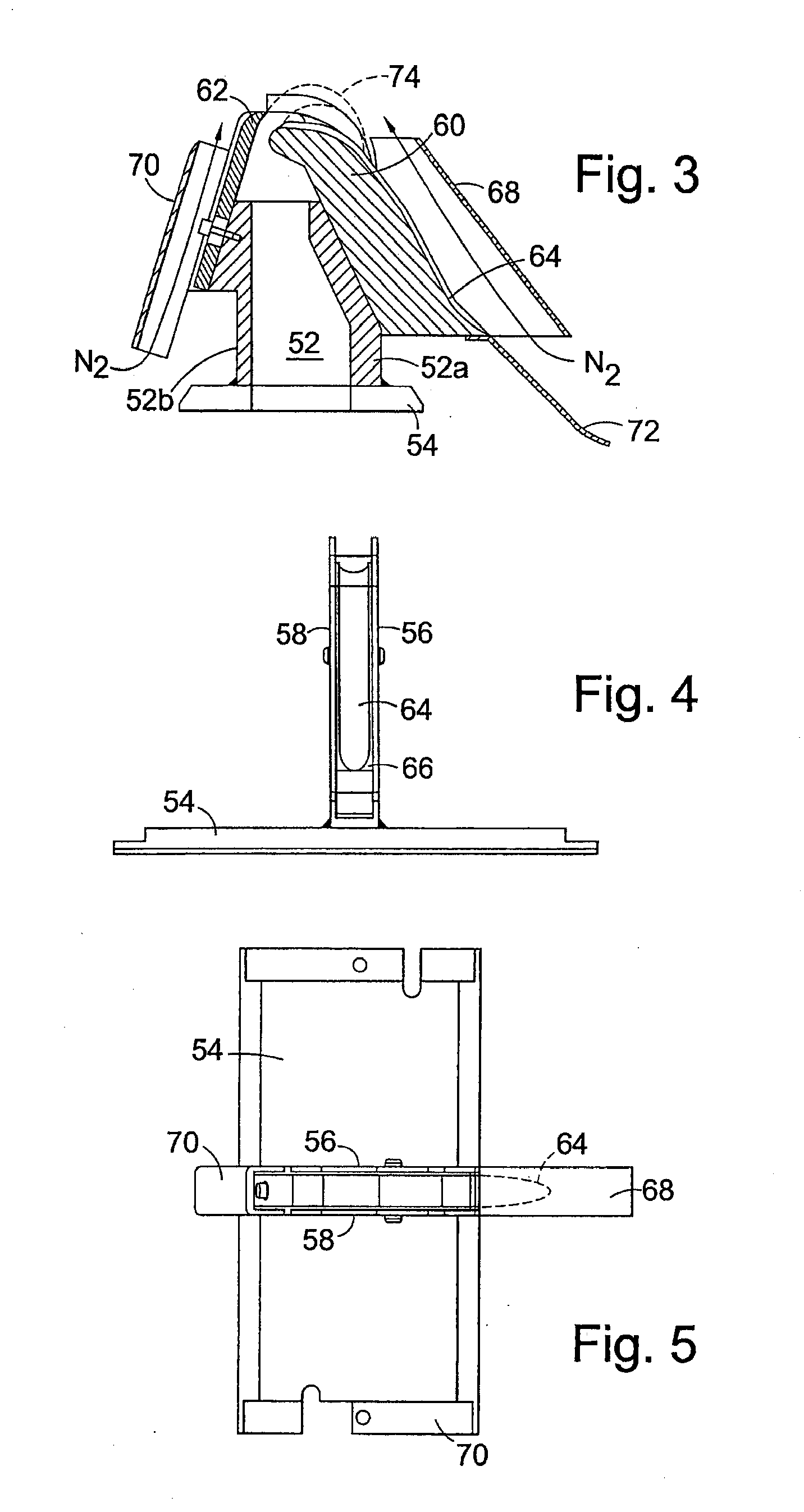
[0046]FIGS. 3 to 5 illustrate a solder nozzle according to the invention. The nozzle 50 has a lower chamber 52 with a plate 54 at its lower end. Plate 54 is fixed direct to a solder conduit or cover of a solder bath as known in the art for solder nozzles, to pump solder through the nozzle. In place of plate 54, a circular flange as for flange 20 of the FIG. 1 embodiment may be provided, for rotatably mounting the nozzle in a structure as shown in FIG. 1. Chamber 52 is formed by two axial end walls 52a, 52b, and a pair of thin side walls 56, 58 mounted on the end walls 52a, 52b. The upper region of chamber 52 is defined between the side walls 56, 58 by a nose 60 and a lip 62 mounted on the respective axial end walls 52a, 52b. Nose 60 has a channel 64 formed in its outer surface 66. Mounted on the nose 60 and lip 62 are conduits 68, 70 for nitrogen gas. The conduits 68, 70 are of the same width as the nose 60 and lip 62 and end walls 52a, 52b, they do not extend widthways of the nozzl...
third embodiment
[0047]FIG. 6 illustrates the invention. In this embodiment, sidewalls or a cover providing a conduit for nitrogen gas have been omitted for clarity. Illustrated in FIG. 6 is a nozzle 80 having a body 82 which is mounted on a plate 84 forming a cover for a solder bath. Solder is pumped into the body 82 which is mounted on a plate 84 forming a cover for a solder bath. Solder is pumped into the body 82 from beneath the plate, as known in the art. Body 82 has an outlet 86 in the form of a cylindrical cross-section spout 88. A jet 90 of solder is pumped from spout 88 and hits an upper edge 92 of a plate 94. The plate 94 serves to stabilise the free end of the solder jet 90.
[0048]If leads to be soldered are passed sideways through the jet 90, in the direction of arrow B-B, there is a tendency for the jet to oscillate sideways and the height of the jet may fluctuate, which may result in a variable quality solder joint.
[0049]Provision of the fin-like plate 92 stabilises the jet against the ...
PUM
| Property | Measurement | Unit |
|---|---|---|
| thick | aaaaa | aaaaa |
| thick | aaaaa | aaaaa |
| thick | aaaaa | aaaaa |
Abstract
Description
Claims
Application Information
 - R&D
- Intellectual Property
- Life Sciences
- Materials
- Tech Scout
- Unparalleled Data Quality
- Higher Quality Content
- 60% Fewer Hallucinations
Browse by: Latest US Patents, China's latest patents, Technical Efficacy Thesaurus, Application Domain, Technology Topic, Popular Technical Reports.
© 2025 PatSnap. All rights reserved.Legal|Privacy policy|Modern Slavery Act Transparency Statement|Sitemap|About US| Contact US: help@patsnap.com


