Check patentability & draft patents in minutes with Patsnap Eureka AI!

Organic el apparatus, method of manufacturing organic el apparatus, electronic apparatus

Active Publication Date: 2010-09-30
SEIKO EPSON CORP
View PDF21 Cites 103 Cited by
  • Summary
  • Abstract
  • Description
  • Claims
  • Application Information

AI Technical Summary

Benefits of technology

[0008]An advantage of some aspects of the invention is to provide an organic EL apparatus having strong mechanical strength and excellent heat releasing performance, a method of manufacturing the organic EL apparatus, and an electronic apparatus.

Problems solved by technology

In the organic EL apparatus using the thin glass substrate, there is a problem in that, since organic EL apparatus is vulnerable to mechanical impact and a thickness thereof is small, it is difficult to treat the organic EL apparatus.
However, there is a problem in that the heat generated at the time of light emission is easily accumulated in the organic EL panel covered with the laminating films.
In addition, there is a problem in that, if it is used for a long time, the light emission characteristic is changed due to the influence of the heat.
Therefore, a gas such as oxygen or water vapor is infiltrated from the outside of the pair of film sheets into the organic EL panel, so that there is a problem in that the life cycle of light emission of the organic EL devices is decreased.
According to the above method, since the manufacturing can be performed by using a general laminating apparatus, a new manufacturing apparatus is unnecessary.

Method used


Image

  • Organic el apparatus, method of manufacturing organic el apparatus, electronic apparatus
  • Organic el apparatus, method of manufacturing organic el apparatus, electronic apparatus
  • Organic el apparatus, method of manufacturing organic el apparatus, electronic apparatus

Examples


first embodiment

Configuration of Organic EL Apparatus

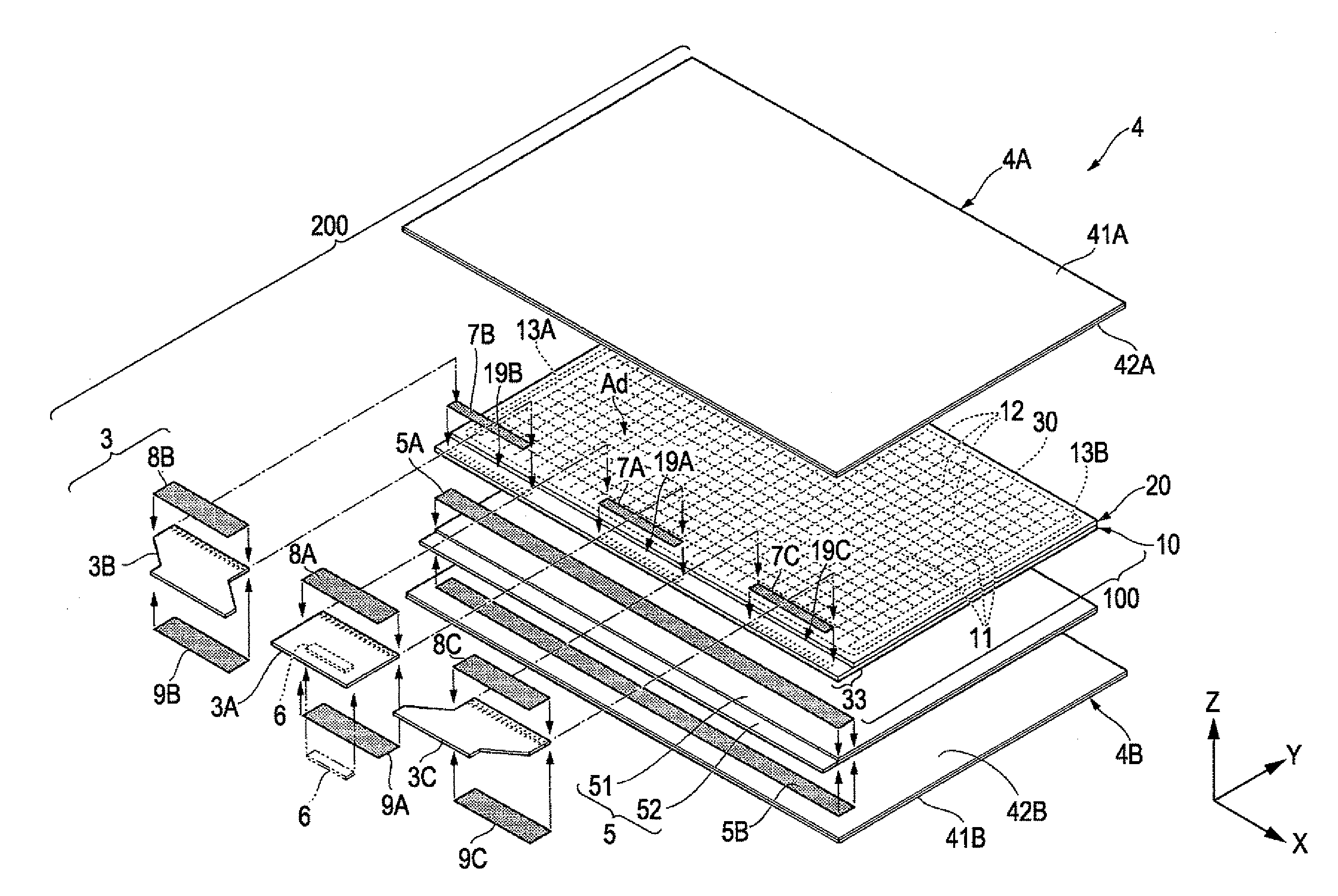
[0070]FIG. 1 is an exploded perspective view illustrating an organic EL apparatus 200 according to a first embodiment of the invention. The organic EL apparatus 200 includes an organic EL panel 100, wiring substrates 3 (wiring substrates 3A, 3B, and 3C) connected to an end portion of the organic EL panel 100, a heat releasing member 5 (a heat releasing sheet 51 and a heat releasing plate 52) disposed on a rear surface (on the side opposite to an observation side) of the organic EL panel 100, and encapsulation structures 4 (a first flexible sheet member 4A and a second flexible sheet member 4B) where the organic EL panel 100, the wiring substrate 3, and the heat releasing member 5 are interposed therebetween to be integrally retained. In addition, in the organic EL apparatus 200, a frame and other additional apparatuses may be provided if necessary, but not shown in FIG. 1.

[0071]The organic EL panel 100 includes a first substrate 10 and a second s...

second embodiment

Configuration of Organic EL Apparatus

[0163]FIG. 10 is an exploded perspective view illustrating an organic EL apparatus 210 according to a second embodiment of the invention. The organic EL apparatus 210 according to the embodiment has a two-side display function using two organic EL panels 100a and 100b.

[0164]The organic EL apparatus 210 includes the first organic EL panel 100a, first wiring substrates 301 (301A, 301B, and 301C) connected to an end portion of the first organic EL panel 100a, a heat releasing member 500 (a first heat releasing sheet 511, a heat releasing plate 520, and a second heat releasing sheet 512) disposed on a rear surface (on the side opposite to an observation side) of the first organic EL panel 100a, a second organic EL panel 100b disposed on the side opposite to the first organic EL panel 100a of the heat releasing member 500, second wiring substrates 302 (302A, 302B, and 302C) connected to an end portion of the second organic EL panel 100b, and encapsul...

third embodiment

Configuration of Organic EL Apparatus

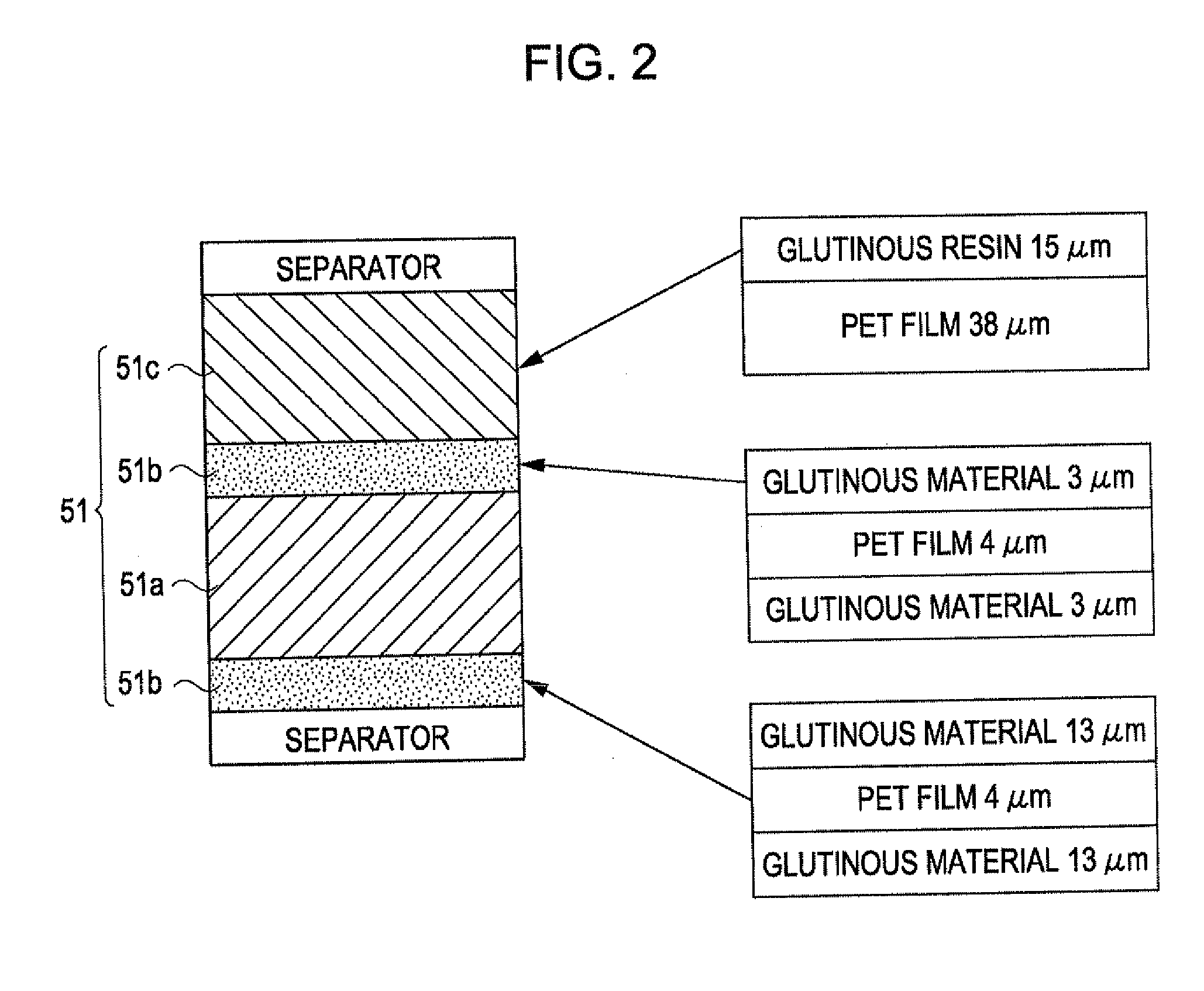
[0188]The organic EL apparatus according to the embodiment is described with reference to FIGS. 11A to 16. FIGS. 11A and 11B are schematic plan views illustrating a configuration of an organic EL apparatus. FIG. 12 is a schematic cross-sectional view illustrating a structure of an organic EL apparatus taken along line XII-XII of FIG. 11A. FIG. 13 is a schematic cross-sectional view illustrating a configuration of a heat releasing sheet.

[0189]As shown in FIGS. 11A and 11B, the organic EL apparatus 220 according to the embodiment includes an organic EL panel 100 which is disposed at the one surface side and an electrophoretic panel 150 which is disposed at the other surface side.

[0190]In addition, hereinafter, the same components as those of the embodiments are denoted by the same reference numerals, and redundant description is appropriately omitted.

[0191]The organic EL panel 100 and the electrophoretic panel 150 overlap through a sheet-shaped hea...


PUM

PropertyMeasurementUnit
Thicknessaaaaaaaaaa
Thicknessaaaaaaaaaa
Thicknessaaaaaaaaaa

Abstract

Provided is an organic EL apparatus including: an organic EL panel including organic EL devices; a heat releasing member; and a pair of film sheets of which at least one is transparent, wherein the organic EL panel and the heat releasing member overlap and are interposed and encapsulated by the pair of film sheets in a state where a portion of the heat releasing member is exposed outside the pair of film sheets.

Description

CROSS REFERENCES TO RELATED APPLICATIONS[0001]The present invention contains subject matter related to Japanese Patent Application No. 2009-077571 filed in the Japanese Patent Office on Mar. 26, 2009 and Japanese Patent Application No. 2009-267189 on Nov. 25, 2009, the entire contents of which are incorporated herein by reference.BACKGROUND[0002]1. Technical Field[0003]The invention relates to an organic EL apparatus having an organic EL (electroluminescence) device, a method of manufacturing the organic EL apparatus, and an electronic apparatus.[0004]2. Related Art[0005]An organic EL apparatus which is a thin, lightly-weighted self-luminous device has been expected to be used for various applications such as a mobile phone, a personal computer, an in-vehicle monitor, or the like. Recently, a glass substrate having high heat resistance has been thinned down to a thickness range of about 50 μm to 100 μm. Therefore, a flexible high-performance organic EL apparatus where peripheral dri...

Claims


Application Information

Patent Timeline
IPC IPC(8): H01L51/52B32B37/12G02F1/167
CPCG02F1/133305G02F1/133603G02F1/167H01L51/5237H01L51/529H01L2924/0002H01L51/56H01L2251/5338H01L2924/00H10K2102/311H10K59/8794H10K71/40H10K59/873H10K59/8722H10K50/87H10K50/84H10K50/844H10K50/8426H10K71/00
Inventor GYODA, KOZO
Owner SEIKO EPSON CORP
Features
  • R&D
  • Intellectual Property
  • Life Sciences
  • Materials
  • Tech Scout
  • Unparalleled Data Quality
  • Higher Quality Content
  • 60% Fewer Hallucinations
Learn More