Antenna devices

Inactive Publication Date: 2010-09-30
TOYOTA CENT RES & DEV LAB INC +1
View PDF4 Cites 49 Cited by
  • Summary
  • Abstract
  • Description
  • Claims
  • Application Information

AI Technical Summary

Benefits of technology

[0010]However, since half-wave-rectified current is generated in the voltage antenna device 400 shown in FIG. 24, a total of at least two tunnel diodes consisting of the electron-selective tunnel diode 442 and the hole-selective tunnel diode 444 are required. In addition, since full-wave-rectified current is generated in the voltage antenna device 410 shown in FIG. 26, a pair of tunnel diodes composed of the electron-selective tunnel diode 442 and the hole-selective tunnel diode 444 and a pair of tunnel diodes composed of the electron-selective tunnel diode 445 and the hole-selective tunnel diode 443 are required, thus requiring a total of at least four tunnel diodes. Thus, the voltage type antenna devices 400 and 410 have the problem of requiring a large number of tunnel diodes. The technology disclosed in the present specification provides a voltage type antenna device having a simple structure.
[0011]As shown in FIG. 25, voltage type antenna devices utilize the phenomenon in which Fermi potential rises at the ends of the an

Problems solved by technology

Thus, the voltage type antenna devices 400 and 410 have

Method used


Image

  • Antenna devices
  • Antenna devices
  • Antenna devices

Examples


first embodiment

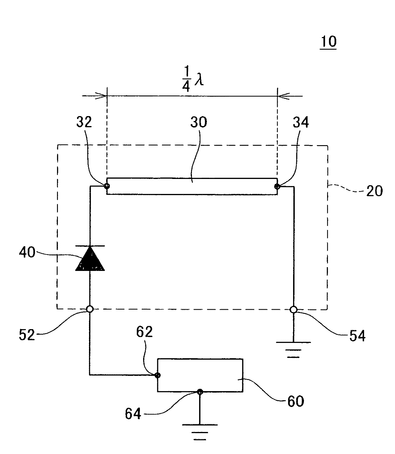
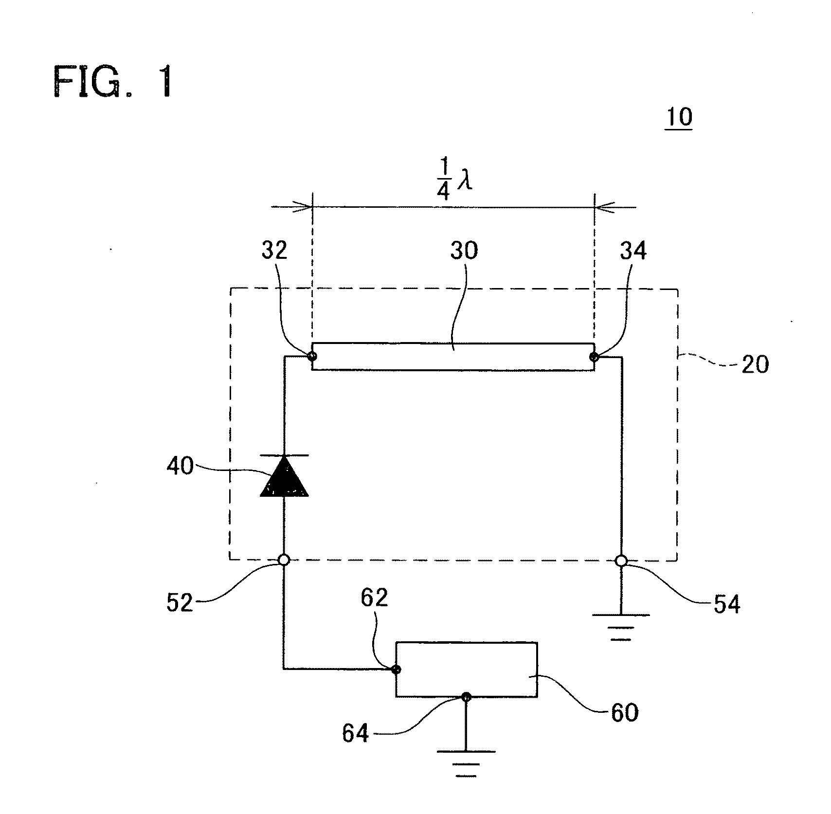
[0054]FIG. 1 shows the configuration of an antenna device 10 for half-wave rectification. The antenna device 10 is provided with an antenna element 20 that supplies current to a load 60. The antenna element 20 has an antenna member 30, a tunnel diode 40, a connecting electrode 52 and a fixed electrode 54.

[0055]The antenna member 30 is electrically conductive and has a linear or flat shape. The antenna member 30 is provided with a portion having a length equal to ¼ of the wavelength λ of light to be received, and the aforesaid portion between one end 32 of that portion (an example of a first portion) and the other end 34 (an example of a second portion) extends along a straight line. The tunnel diode 40 is connected between the one end 32 of the antenna member 30 and the connecting electrode 52, and selectively allows transmission of hot electrons energized to a predetermined energy level. The cathode of the tunnel diode 40 is connected to the one end 32 of the antenna member 30, whi...

second embodiment

[0058]FIG. 4 shows the configuration of an antenna device 100 for full-wave rectification. The antenna device 100 is provided with an antenna element 120 that supplies current to a load 160. The antenna element 120 has an antenna member 130, a first tunnel diode 142, a second tunnel diode 144, a first connecting electrode 152, a second connecting electrode 156, and a fixed electrode 154.

[0059]The antenna member 130 is electrically conductive and has a linear or flat shape. The antenna member 130 is provided with a portion having a length equal to ½ of the wavelength λ, of light to be received, and the aforesaid portion between one end 132 of that portion and the other end 136 extends along a straight line. The portion of the antenna member 130 that extends along the straight line includes a first antenna member 133 and a second antenna member 135. The first antenna member 133 and the second antenna member 135 extend symmetrically with respect to a center portion 134 (and these are e...

example 1

[0065]The following provides a detailed explanation of an antenna device that embodies the technology disclosed in the present specification. Furthermore, the antenna device explained below is used to receive light having a wavelength shorter than that of infrared light, and more specifically, is used to receive light of a wavelength of 2 μm or less. More preferably, the antenna device explained below is used to receive light within the range of infrared light to visible light, and more specifically, is used to receive light of a wavelength within the range of 0.2 to 2 μm. The antenna device explained below can be applied to technologies for wireless transmission and / or reception of electrical power and technologies for generating electrical power from sunlight.

[0066]FIGS. 9A and 9B show the configuration of an antenna element 220 provided in an antenna device of the first example. The antenna element 220 is a basic unit of the antenna device. FIG. 9A schematically shows a longitudi...


PUM


Abstract

An antenna device is provided with a first connecting electrode, a first tunnel diode, a first antenna member and a fixed electrode. The first connecting electrode is configured to be connected to a fixed potential via a load. The first tunnel diode has a pair of electrodes. One of the electrodes of the first tunnel diode is connected to the first connecting electrode, and the other electrode of the first tunnel diode is connected to the first antenna member. The first antenna member has a conductive property and includes a first portion and a second portion. The first portion of the first antenna member is connected to the other electrode of the first tunnel diode. The fixed electrode is connected to the second portion of the first antenna member. The fixed electrode is configured to be connected to the fixed potential.

Description

CROSS-REFERENCE TO RELATED APPLICATIONS[0001]This application claims priority under Paris convention based on Japanese Patent Application No. 2009-082558 filed on Mar. 30, 2009, the contents of which are hereby incorporated by reference into the present application.TECHNICAL FIELD[0002]The present invention relates to an antenna device for transmitting and / or receiving light. The present invention also relates to an antenna device for receiving light and transducing a light energy to an electric energy.DESCRIPTION OF RELATED ART[0003]Technologies for transmitting and / or receiving light using an antenna device are required in various fields. Developments of technologies that use antenna devices, e.g., in transmission and / or reception of information, wireless transmission and / or reception of electrical power using light as a medium, and generating electrical power from sunlight, are in progress. An antenna device referred to as a rectenna, which receives light with an antenna member a...

Claims


Application Information

Patent Timeline
IPC IPC(8): F21K99/00H01Q1/50H01Q9/06
CPCH01Q1/2283H01Q23/00H01Q9/30H01Q1/38
Inventor ITO, TADASHIOKAMOTO, ATSUTOMOTOHIRO, TOMOYOSHINOMURA, TSUYOSHIHANAZAWA, MASAHIROITO, TOSHIYASUMIYAZAKI, TAKESHIUENO, YUKIHISA
Owner TOYOTA CENT RES & DEV LAB INC
Why Eureka
Try Eureka