Device to synchronize the change of the driving mode of an electromagnetic load

a technology of electromagnetic load and driving mode, which is applied in the direction of synchronous motor starters, h-bridge head driver circuits, magnetic recording, etc., can solve the problems of deteriorating system performance in terms of accuracy and arrival time on tracks, and achieve the effect of reducing the time required for changing

Active Publication Date: 2010-09-30
STMICROELECTRONICS SRL
View PDF13 Cites 7 Cited by
  • Summary
  • Abstract
  • Description
  • Claims
  • Application Information

AI Technical Summary

Benefits of technology

[0019]In view of the state of the art, the present disclosure provides a device to synchronize the change of the driving modality of an electromagnetic load that minimizes the time required to change the driving modality and, specifically, limits the variation of the mean value of the current in the voice coil motor during the change of the driving modality, if the electromagnetic load is a voice coil motor.

Problems solved by technology

This current glitch is a discontinuity existing in the power-assisted control system which places the heads on the disk tracks and which is moved by the voice coil motor 3, and may deteriorate the system performance in terms of accuracy and arrival time on the tracks.

Method used


Image

  • Device to synchronize the change of the driving mode of an electromagnetic load
  • Device to synchronize the change of the driving mode of an electromagnetic load
  • Device to synchronize the change of the driving mode of an electromagnetic load

Examples


Embodiment Construction

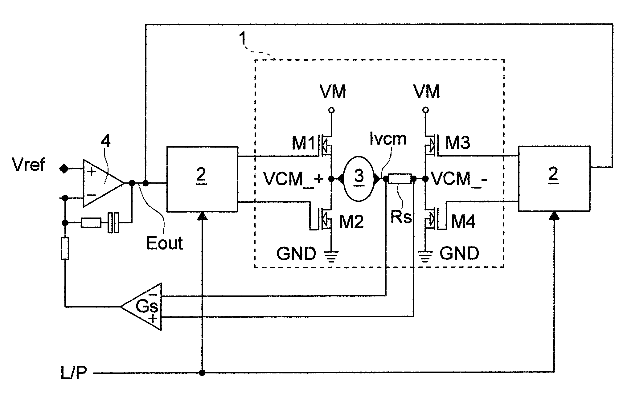
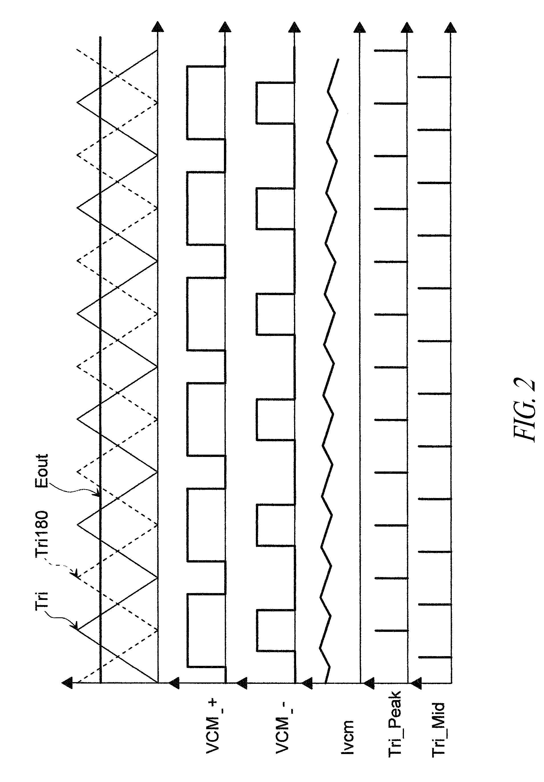
[0040]FIG. 6 shows a device 100 to synchronize the change of driving modality of an electromagnetic load 3 in accordance with one aspect of the present disclosure.

[0041]The device 100 has a gate device, in this case an OR gate 101 with a first input 102 that receives a control signal L / P to change the operation modality of an electromagnetic load 3 passed through by a current Ivcm from a first operation modality to a second operation modality or vice versa, and a second input 104 to receive a signal Tri_Peak, Tri_Mid representative of the passage of the current Ivcm passing through the load 3 for substantially its mean value IM. The device 100 includes a logic circuit 106 adapted to synchronize the control signal L / P for changing from the first operation modality to the second operation modality or vice versa of the electromagnetic load with the signal representative of the passage of the current Ivcm passing through the load 3 for substantially its mean value IM. The circuit 106 is...


PUM

PropertyMeasurementUnit
currentaaaaaaaaaa
voltageaaaaaaaaaa
voltagesaaaaaaaaaa

Abstract

A device for the change of the driving mode of an electromagnetic load from a first operating mode with pulse width modulation to a second operating mode that is linear by means of switching circuits. During a first operating mode, each of two outputs has a voltage value ranging from a first reference voltage to a second reference voltage. The device adapted to synchronize a change command signal from a first operating mode to a second operating mode of the electromagnetic load with the signal representative of the flow of current circulating within the load at substantially its average value and adapted to generate a first command signal in response to the synchronization.

Description

BACKGROUND[0001]1. Technical Field[0002]The present disclosure relates to a device to synchronize the change of the driving modality of an electromagnetic load, especially a voice coil motor used in applications for computer hard disks.[0003]2. Description of the Related Art[0004]In the state of the art, it is known that the reading and writing heads of a hard disk for computers are moved by a voice coil motor.[0005]The linear modality current control of a voice coil motor in hard disk applications is accomplished by means of a power stage in a bridge configuration operating in class AB for the known properties of good linearity and cross distortion.[0006]In order to limit the power dissipated by the output stage, during the track search operations, systems of PWM current control are used.[0007]A method to PWM drive a power stage in a bridge configuration is described in Patent EP 760552. FIG. 1 shows the diagram of a power stage 1 with driving circuits 2 and voice coil motor 3 as d...

Claims


Application Information

Patent Timeline
Patent Type & Authority Applications(United States)
IPC IPC(8): G05B11/28H01F27/42
CPCH02P6/08H02P6/085G11B5/5547H02P25/028G11B5/022H02P6/22H02P25/034
Inventor GALBIATI, EZIOPERITORE, ROBERTOBARTOLINI, MICHELEMIRABELLI, AGOSTINO
Owner STMICROELECTRONICS SRL
Why Eureka
Try Eureka