Enclosure for Confining the Released Chemicals of Electrical Devices

a technology for electrical devices and enclosed enclosures, which is applied in the direction of electrical apparatus casings/cabinets/drawers, instruments, gaseous cathodes, etc., can solve the problems of worrisome, flame retardant suspected of causing health problems, and blood samples of flame retardants around the world, so as to achieve convenient disassembly

Inactive Publication Date: 2010-09-30
STRONG DANIEL
View PDF11 Cites 11 Cited by
  • Summary
  • Abstract
  • Description
  • Claims
  • Application Information

AI Technical Summary

Benefits of technology

[0022]Moreover, the present invention also provides a heat transfer apparatus for a housed electrical device. The apparatus includes a housing portion and a displaceable heat conductive mass. As the housing portion is closed, the displaceable heat conductive mass is contacted and thermal energy flows from a housed electrical device to the housing portion. As the housing portion is opened, contact is concluded. Thereby, the electrical device transfers heat directly to its housing and is easily detached from its housing as well.

Problems solved by technology

Although wires, circuit boards, and plastic housings of modern devices are embedded with flame retardants to conform with current fire safety standards, some widely used flame retardants are suspected of posing health risks.
Older devices also contain dangerous chemicals including heavy metals and polychlorinated biphenyls (PCBs) and can continue to release chemicals into the air over their entire life span.
This is especially worrisome because, as a device's components warm up, flame retardants are outgassed into the surrounding environment and can be inhaled by people.
A 2004 study conducted by the coalition found that flame retardants suspected of causing health problems are showing up in blood samples around the world.
Some electrical devices, although small in size, release a large amount of chemicals into the air.
Such chemicals are especially troublesome to some people.
Additionally, the inventor has repeatedly found that maintaining a flow of outdoor air through the environment surrounding the computer increases the length of exposure time which can be tolerated before negative physical symptoms are experienced.
An electrical device's heat must be dissipated or the device can sustain damage.
When fans are necessary to move the air, they are often found to be too noisy for workplace and home environments.
Heat transfer apparatuses, such as heat pipes and conductive heat transfer assemblies, can effectively transfer heat from an enclosed device directly to portions of the enclosure, but their use can pose an inconvenience.
In addition, the liquescent synthetic filler materials used to seal enclosures usually release undesirable odors and undesired chemicals into the air.
Furthermore, such sealant materials cannot be reused.
However, enclosures for electrical devices heretofore have not been designed to be sealed with wax.
Enclosures for electrical devices often have doors to give access to enclosed devices, but door seals have problems.
It is difficult to create an airtight seal.
In addition, over time, as the door is repeatedly opened and closed, the seal may be weakened, gradually losing its effectiveness.
However, in such an arrangement, connecting the enclosed device to the top enclosure member presents a challenge.
Thus, there is no way to access the enclosed space for the purpose of attaching the heat transfer apparatus.
Unfortunately, to the best of the inventor's knowledge, no such heat transfer configuration for an electrical device enclosure currently exists.
The rest of the enclosures are too noisy, bulky, or have cooling systems that are too expensive.
Inventions have been made to protect users from electrical radiation, but these inventions do not protect users from released chemicals.
Likewise, patented enclosures for electrical devices do not offer an acceptable solution.
Immersing devices in liquid is not a practical way to enclose most devices.
It relies too heavily on the use of fans or pumps.
It would be too noisy.
It is overly complicated.
It is not practical for most existing devices.

Method used


Image

  • Enclosure for Confining the Released Chemicals of Electrical Devices
  • Enclosure for Confining the Released Chemicals of Electrical Devices
  • Enclosure for Confining the Released Chemicals of Electrical Devices

Examples


Embodiment Construction

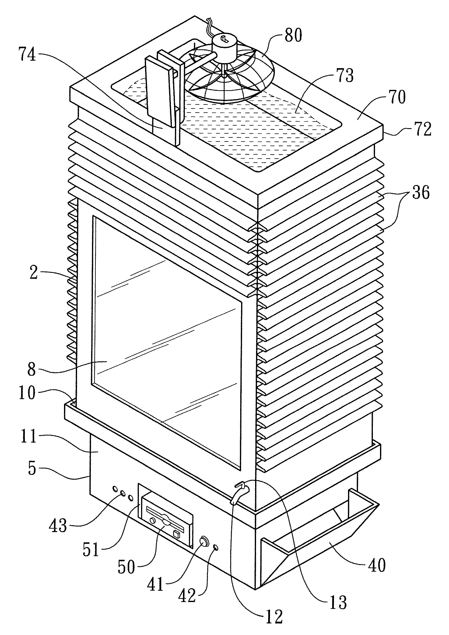
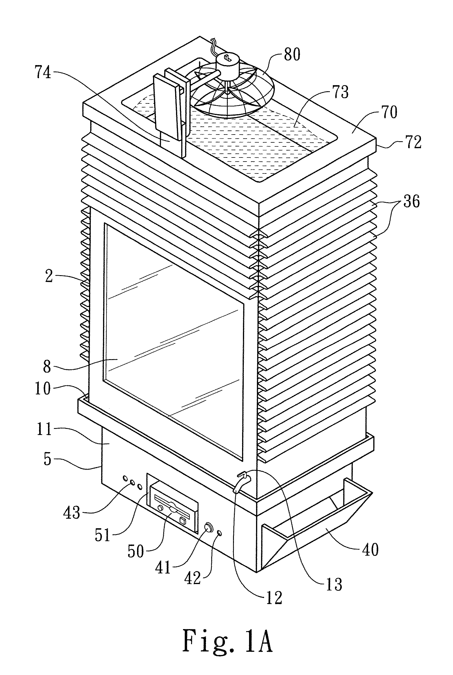
[0075]A preferred embodiment of the present invention is shown in FIGS. 1A-1I. As shown in FIG. 1A, it is an enclosure for a personal computer. It has two members. It has a top member 2 and a bottom member 5. Both members are made from aluminum. Aluminum is the preferred material due to its good thermal conductivity and its resistance to water corrosion. Other heat conductive and water resistant materials could be used, such as copper or ceramic.

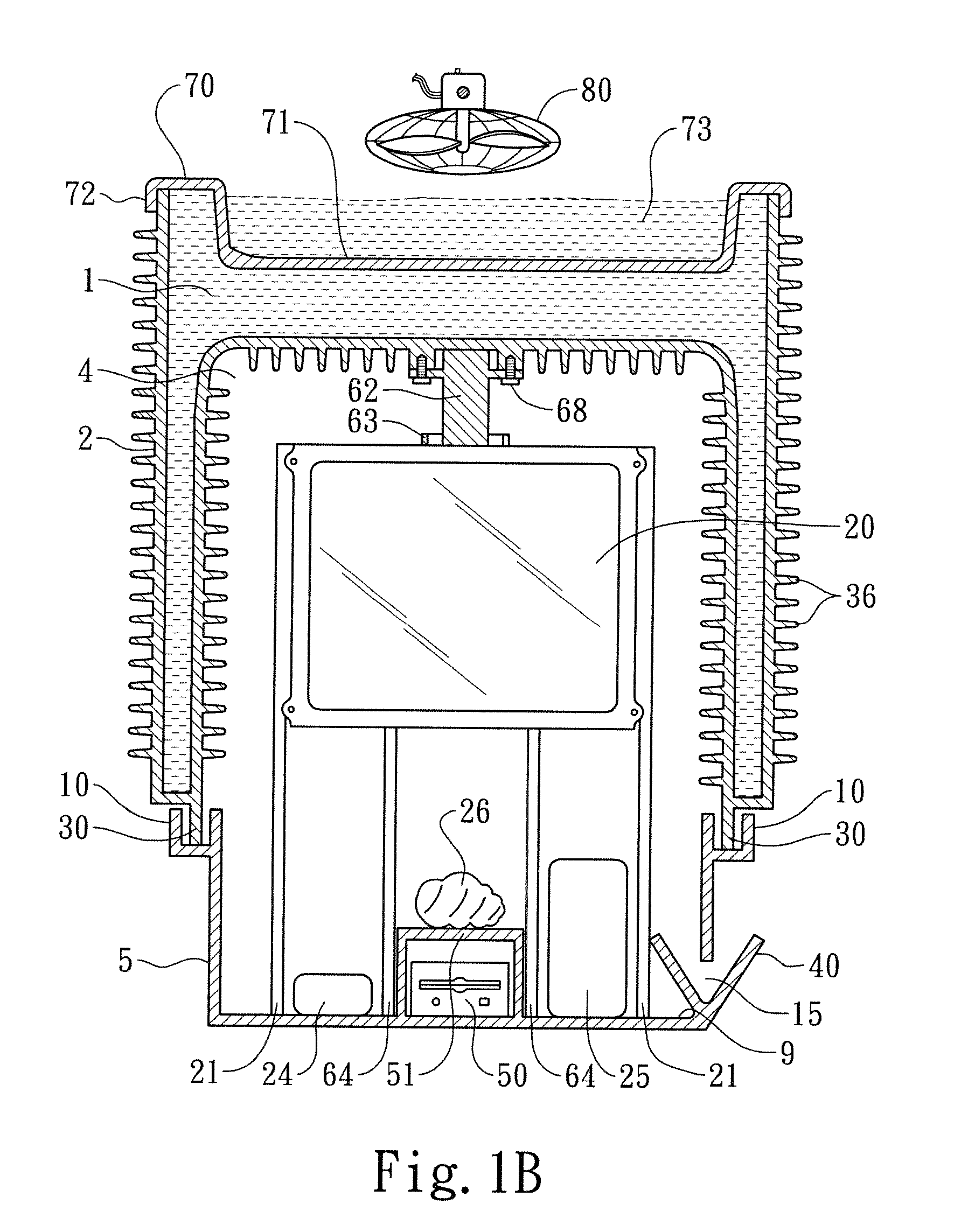
[0076]As shown in FIG. 1B, lining most of the top member 2 are fins 36. The fins 36 improve the thermal absorption and dissipation of the enclosure. The fins 36 face inward in the enclosed space 4 and outward on the outside.

[0077]The top member 2, which can hold material, is hereinafter referred to as the vessel. The bottom member 5 on which electrical devices are secured or placed is hereinafter referred to as the base.

[0078]As shown in FIG. 1A, the base 5 is rectangular and trough shaped. The base 5 has a perimeter wall 11 around its perim...


PUM


Abstract

An enclosure comprised of at least two members creates a sealable enclosed space. At least one of the members is a vessel that absorbs thermal energy from the enclosed space and transfers it into material it holds. Built into the enclosure is a connection means for connecting an enclosed device to outside devices. Disclosed is a moat based sealing configuration for a top and base enclosure. Also disclosed is an easily detachable heat transfer apparatus in which thermal energy transfer contact from an enclosed device to a housing member is formed as a housing portion is moved into closed position and concluded as the housing portion is moved away from closed position.

Description

BACKGROUND OF THE INVENTION[0001]1. Field of the Invention[0002]The present invention relates to housings for electrical devices and, more particularly, to tightly sealed enclosures for electrical devices to protect humans from the chemicals released by electrical devices.[0003]2. Description of the Prior Art[0004]Outgassing is a term referring to the release of a gas that was trapped, frozen, absorbed, or adsorbed in some material. In reference to indoor air quality, outgassing is sometimes referred to as offgassing. Household items that release chemicals into the air include plastic, plywood, particleboard, carpeting, vinyl flooring, adhesives, paints, fabrics, and much more. The rate of outgassing tends to correspond directly with the temperature of an item; the warmer its temperature, the more chemicals it releases into the environment.[0005]Although wires, circuit boards, and plastic housings of modern devices are embedded with flame retardants to conform with current fire safe...

Claims


Application Information

Patent Timeline
Patent Type & Authority Applications(United States)
IPC IPC(8): H05K7/20H05K5/06
CPCG06F1/16G06F1/20G06F1/183G06F1/181
Inventor STRONG, DANIEL
Owner STRONG DANIEL
Why Eureka
Try Eureka