Sealing Segment and Sealing-Segment Arrangement

a sealing segment and sealing segment technology, applied in the direction of bearings, leakage prevention, jet propulsion plants, etc., can solve the problems of lasting negative impact on the life limited relative movement of the two structural components with respect to one another, and costly sandwich construction, so as to enhance the sealing effect between adjacent sealing segments, and increase the elasticity of the sealing segment

Active Publication Date: 2010-09-30
MAN ENERGY SOLUTIONS SA
View PDF21 Cites 32 Cited by
  • Summary
  • Abstract
  • Description
  • Claims
  • Application Information

AI Technical Summary

Benefits of technology

[0012]In another embodiment, the sealing segment comprises two sheet-like sealing elements which are connected to one another in the web area. For technical reasons relating to manufacture, it is advantageous when the two sealing elements are identically shaped. Free end portions of the sealing elements can be at a distance from one another in the assembled state. When using a plurality of sealing segments axially one behind the other, the sealing effect between adjacent sealing segments can be enhanced in that the sheet-like sealing elements are arranged so as to be offset relative to one another in longitudinal direction, so that there is a step-like material overlapping between the sealing segments.
[0013]In another embodiment, a transverse slit that can extend up to the web is formed in at least one sealing body to increase the elasticity of the sealing segment. The elasticity can be further increased in that a plurality of transverse slits are alternately provided in one sealing body so as to extend along the web into the other sealing bodies.
[0014]To improve the cooling of the sealing segments and sealing surfaces, the sealing bodies can be at least partially perforated. Alternatively,

Problems solved by technology

One of the disadvantages of this sealing segment is the costly sandwich construction.
It is further disadvantageous that this sealing segment only allows a rotational relative movement between the two structural component parts.
The maximum relative movement of the two str

Method used


Image

  • Sealing Segment and Sealing-Segment Arrangement
  • Sealing Segment and Sealing-Segment Arrangement
  • Sealing Segment and Sealing-Segment Arrangement

Examples


Embodiment Construction

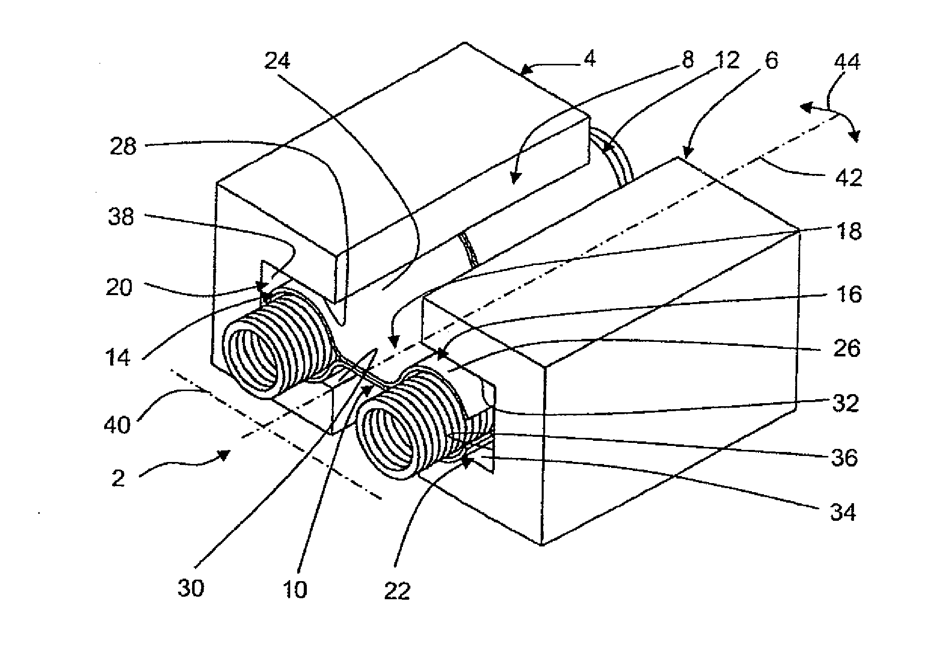
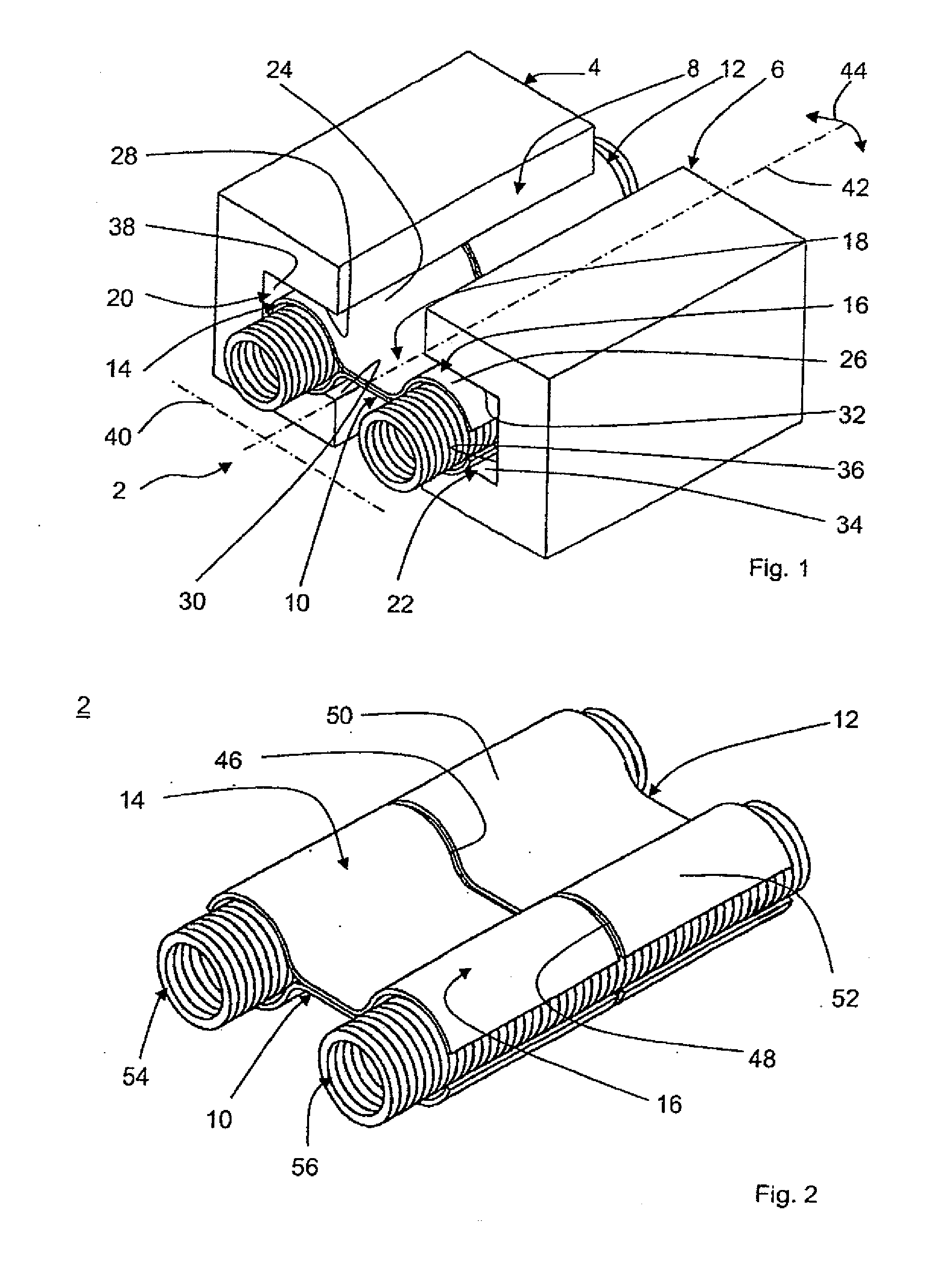
[0028]FIG. 1 shows a three-dimensional view of a sealing segment arrangement 2 according to the present invention for connecting two adjacent structural component parts 4, 6 so as to be sealed with respect to pressure and temperature. The structural component parts 4, 6 are shown in a highly simplified manner and are separated from one another by a gap 8. The sealing segment arrangement 2 comprises a plurality of metal sealing segments, two of which 10, 12 are shown by way of example.

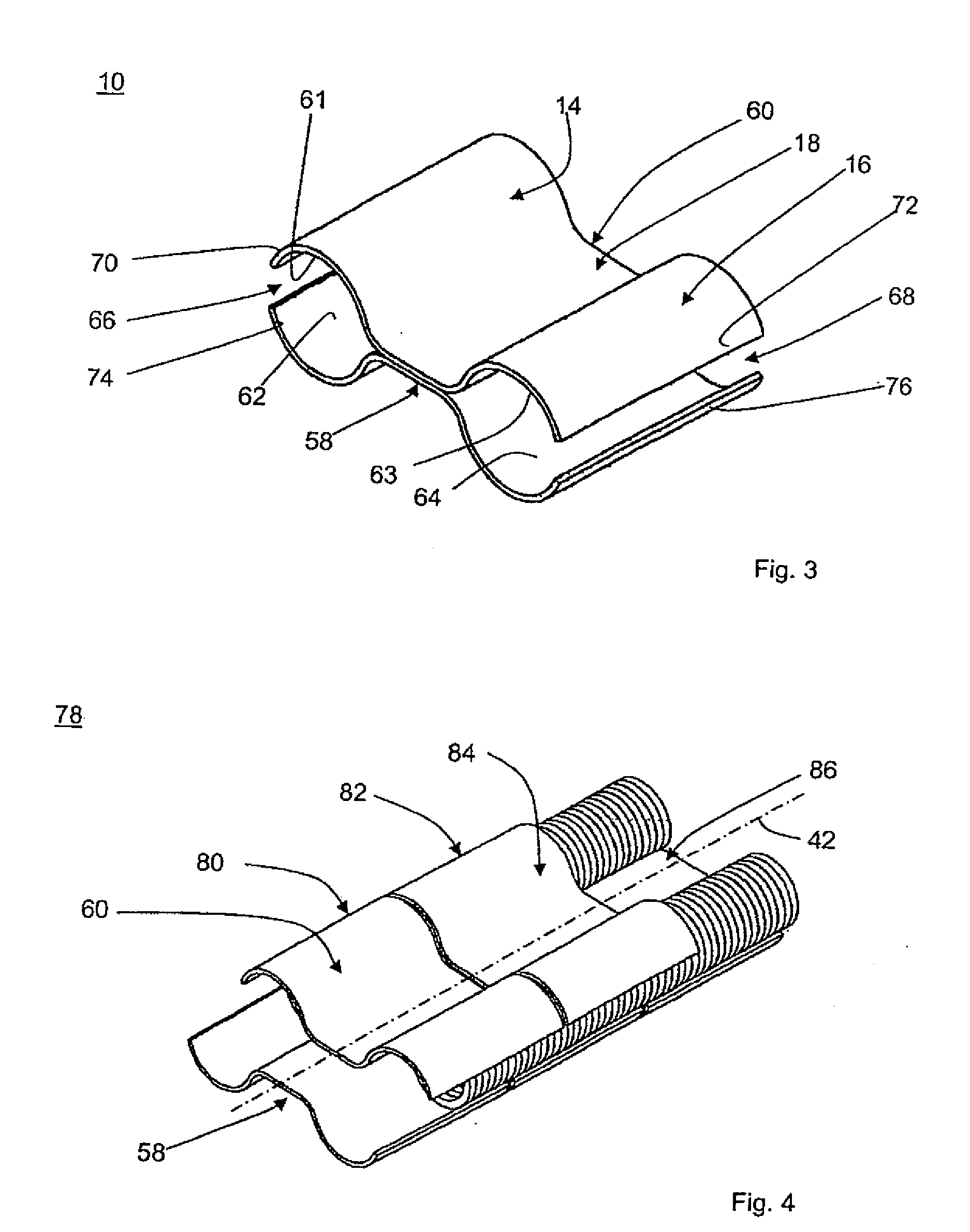
[0029]Each sealing segment 10, 12 has two axially parallel, cylindrical sealing bodies 14, 16 which are connected to one another in each instance by a web 18 which is constructed so as to have an extensive surface. The sealing bodies 14, 16 are radially springing and are partially enclosed in a U-shaped, rectangular longitudinal groove 20, 22 of the structural component parts with inner groove surfaces 28, 30 and 32, 34, respectively, extending parallel to one another in pairs. The sealing bodies 14, 16...


PUM


Abstract

A sealing segment for sealingly connecting two structural components parts which are movable relative to one another, with two sealing bodies which are connected to one another by a web and which can be arranged in recesses of the structural component parts in an articulated manner, and a sealing segment arrangement with a plurality of sealing segments of this type, and a flow machine with a sealing segment arrangement of this type.

Description

[0001]PRIORITY CLAIM[0002]This is a U.S. national stage of application No. PCT / EP2008 / 009257, filed on Nov. 3, 2008. Priority is claimed on the following application: Country: Germany, Application No.: 10 2007 062 681.0, Filed: Dec. 24, 2007, the content of which is / are incorporated here by reference.FIELD OF THE INVENTION[0003]The present invention is directed to a sealing segment according to claim 1 for sealingly connecting two structural components parts which are movable relative to one another, a sealing segment arrangement, and a flow machine with a sealing segment arrangement of this type.BACKGROUND OF THE INVENTION[0004]Sealing segments for sealingly connecting adjacent structural component parts are known per se. A sealing segment allowing a relative movement of adjacent structural component parts with respect to one another is disclosed, for example, in DE 2453645. This sealing segment comprises a plurality of metal rings and plastic rings in a sandwich-type construction ...

Claims


Application Information

Patent Timeline
IPC IPC(8): F16C33/74F16C29/02F16C33/02F16C33/06F16J15/16F02C7/28
CPCF01D9/023F01D11/005F05D2230/642F05D2240/11F16J15/0893
Inventor ASCHENBRUCK, EMILBLASWICH, MICHAELEL MASALME, JAMANREISS, FRANK
Owner MAN ENERGY SOLUTIONS SA
Why Eureka
Try Eureka