
Method and Apparatus for Increasing the Capacity of A Data Communication Channel

apacity technology, applied in the field of data communication, can solve the problems of bit smear at the receiver end, deterioration of the quality of modulated optical signals, and overloaded optical infrastructure, and achieve the effect of efficient increasing the capacity of a data communication channel

Active Publication Date: 2010-09-30
MULTIPON NETWORKS
View PDF4 Cites 12 Cited by
  • Summary
  • Abstract
  • Description
  • Claims
  • Application Information

AI Technical Summary

Benefits of technology

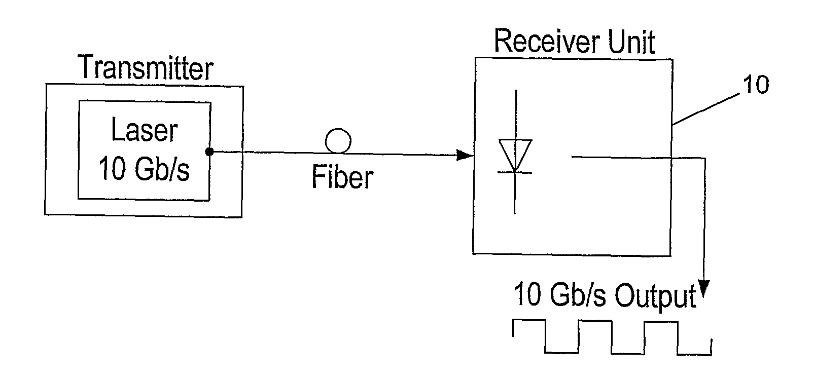
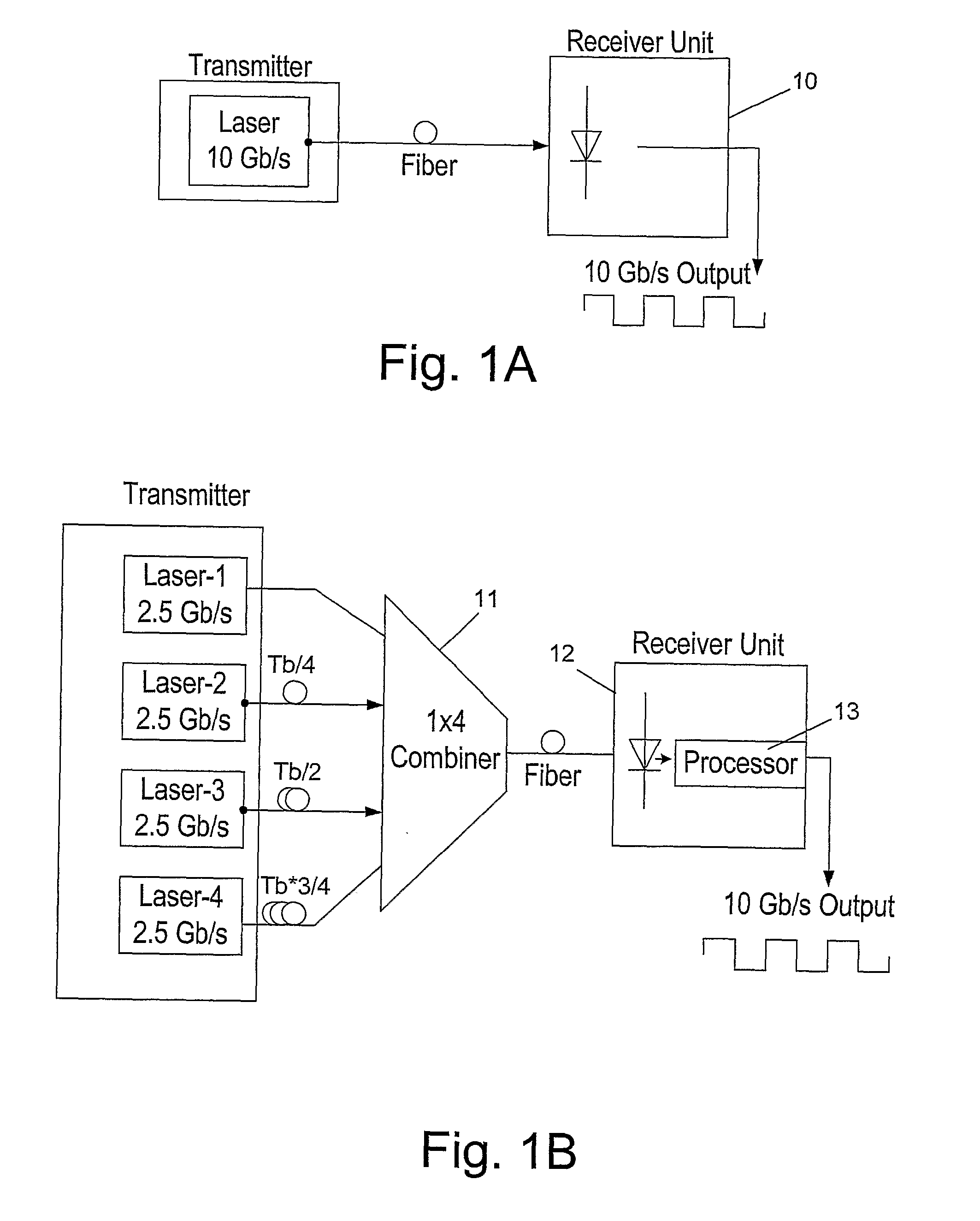
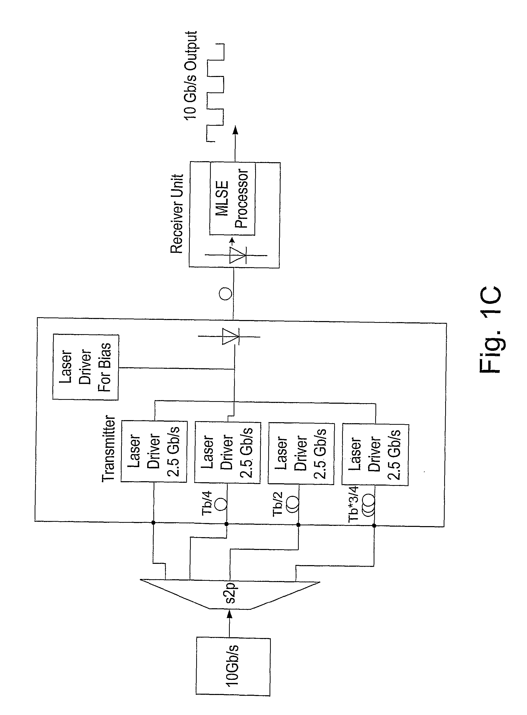
[0019]The present invention is directed to a method for efficiently increasing the capacity of a data channel, such as an optical channel which can be over 100 km long, that can operate in a given data rate B, which can be 10 Gb/s PON. Accordingly, N modulated data streams with a bit rate of B/N and a bit-time of N/B are generated at the transmission end (e.g., by using low cost laser sources with direct modulation), to be simultaneously transmitted from a transmission end to a receiving end of the channel. A shift of 1/B*N between the first, modulated data stream and each of its N−1 subsequent modulated data streams is generated, e.g., by using time delay or p...

Problems solved by technology

Since there is a growing demand for such wideband services, even the optical infrastructure may become overloaded.
However, by doing so, the quality of the modulated optical signal is deteriorated due to transient effects named transient chirp, (e.g., unstable frequency) that generally appear during the rise and fall times of the amplitude of the laser signal, and frequency changes due to laser intensity changes named adiabatic chirp.
These frequency broadening effects result in bit smear at the receiver end.
In addition, the quality of the modulated optical signal is deteriorated due to chromatic dispersion, which is a phenomenon that causes the separation of an optical wave confined to a waveguide (e.g., an optical fiber) into spectral components with different wavelengths, due to a dependence of the wave's velocity on its wavelength and the dispersion of the materials they propagate through.
Such dispersion leads to signal degradation because of the varying delay in arrival time between different components of a signal distorts the signal in time.
The problem becomes more severe as the frequency of the laser source increases with time (producing a chirp signal).
However, such reduction also reduces the data rate of the transmitted signal.
However, this solution still limits the capacity of the data channel, since only a single channel transmits at each time slot.
In addition, this requires reducing the bit-time (i.e., increasing the transmission rate), which is a costly solution.
However, this solution requires several high quality laser sources with different frequencies and is therefore, costly.
However, this solution is also problematic, since the external modulator is costly, and has insertion-loss that attenuates the signal.
All the methods described above have not yet provided satisfactory solutions to the problem of efficiently increasing the capacity of an optical data channel in a low cost manner for Passive Optical Network (PON) application, which eliminates the drawbacks of prior-art solutions.

Method used


Image

  • Method and Apparatus for Increasing the Capacity of A Data Communication Channel
  • Method and Apparatus for Increasing the Capacity of A Data Communication Channel
  • Method and Apparatus for Increasing the Capacity of A Data Communication Channel

Examples


Embodiment Construction

[0041]The present invention proposes a method that combines properties of time division multiplexing with multilevel multiplexing of signals, in order to efficiently increase the channel capacity. This unique combination is called hereinbelow Time Division Multilevel Multiplexing (TDMM) and allows increasing the bandwidth of data that can be transmitted through the channel by a factor of N (N represents the number of levels of the multilevel signal) or alternatively, allows the transmission of N independent channels through the fiber, or any combination thereof. The proposed method increases the bandwidth cost effectiveness and reduces the impact of fiber chromatic dispersion.

[0042]The system and method proposed by the present invention allow using low-cost low-frequency lasers with indirect modulation for high-speed fiber-optic transmission, rather than using a high-frequency laser that requires expensive direct modulation. In addition, the proposed method effectively mitigates the...


PUM


Abstract

Method for efficiently increasing the capacity of an optical channel which can operate in a given data rate B, by generating N modulated data streams with a bit rate of B / N and a bit-time of N / B at the transmission end, to be simultaneously transmitted from a transmission end to a receiving end of the channel. A shift of 1 / B*N between the first modulated data stream and each of its N−1 subsequent modulated data streams is generated using time delay or phase shifting and then the first modulated data stream and its shifted subsequent modulated data streams are combined into a composite multilevel signal with up to N levels and the composite multilevel signal is transmitted to a receiving end of the channel. At the receiving end, the composite multilevel signal is sampled N times during each bit-time, in order to obtain a vector with N elements at each time, such that each element has N+1 possible values and corresponds to the order of a sample. Each of the N modulated data streams are reconstructed by vectorial MLSE, preformed for each element by calculating the joint conditional PDF.

Description

FIELD OF THE INVENTION[0001]The present invention relates to the field of data communication. More particularly, the invention relates to a method and apparatus for efficiently increasing the capacity of an optical data channel by performing a combination of Time Division Multiplexing with Multilevel Signals Multiplexing.BACKGROUND OF THE INVENTION[0002]Many modern telecommunications data channels use optical fibers for data transmission, due to their higher bandwidth and low attenuation. Today, optical fiber infrastructure start reaching apartment buildings and even private homes, so as to allow providing wideband services, such as Triple Play (a Triple Play service bundles high-speed Internet access, television, such as TV broadcast or Video on Demand and telephone service over a single broadband connection) and High-Definition television (HDTV). Since there is a growing demand for such wideband services, even the optical infrastructure may become overloaded.[0003]Data in an optic...

Claims


Application Information

Patent Timeline
IPC IPC(8): H04B1/66H04B10/00
CPCH04B10/541H04J7/00H04J3/047H04B10/69
Inventor SADOT, DANKATS, GILAD
Owner MULTIPON NETWORKS
Learn More